|
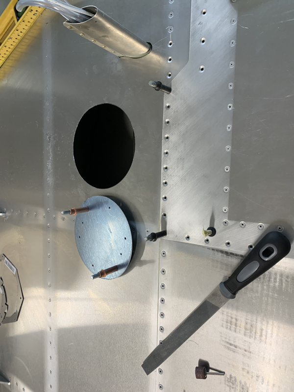
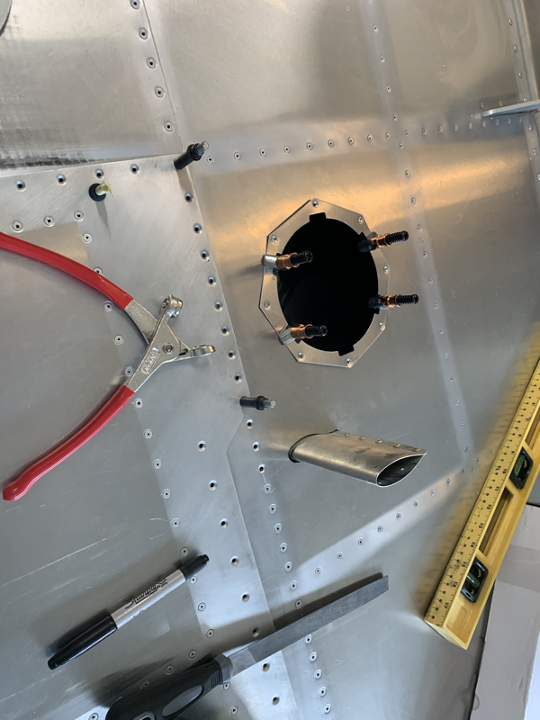
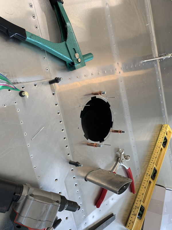
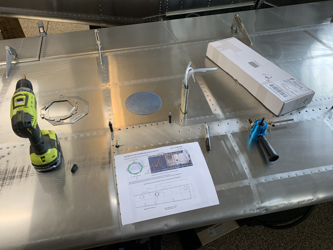
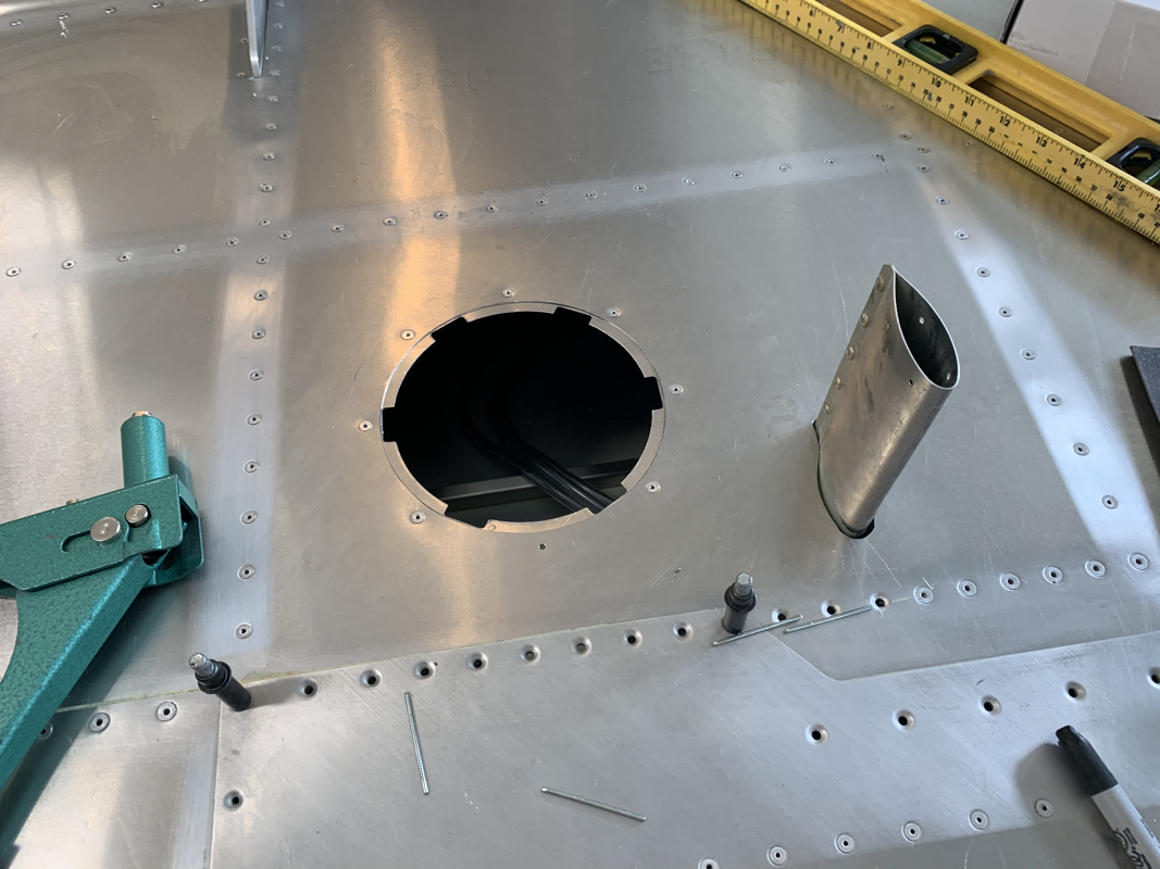
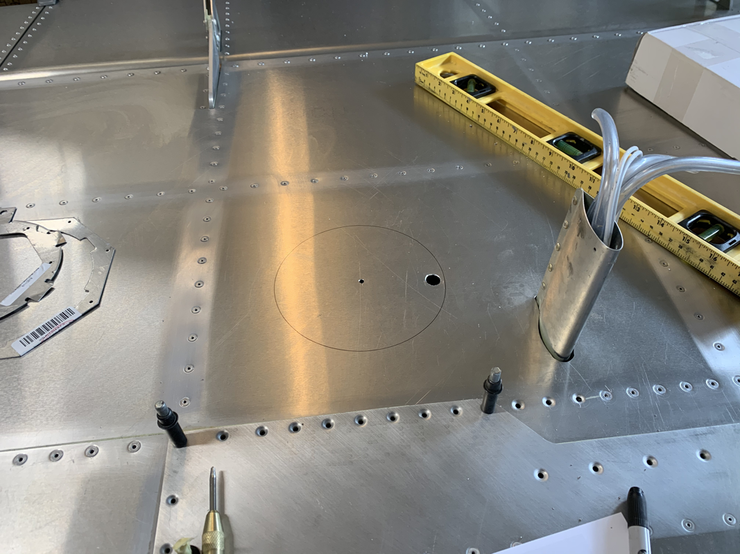
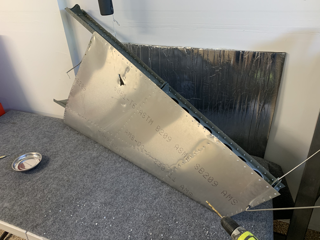
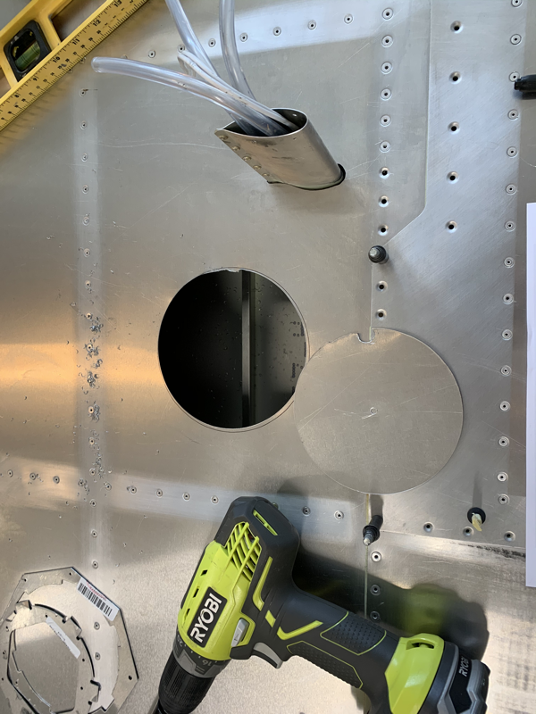
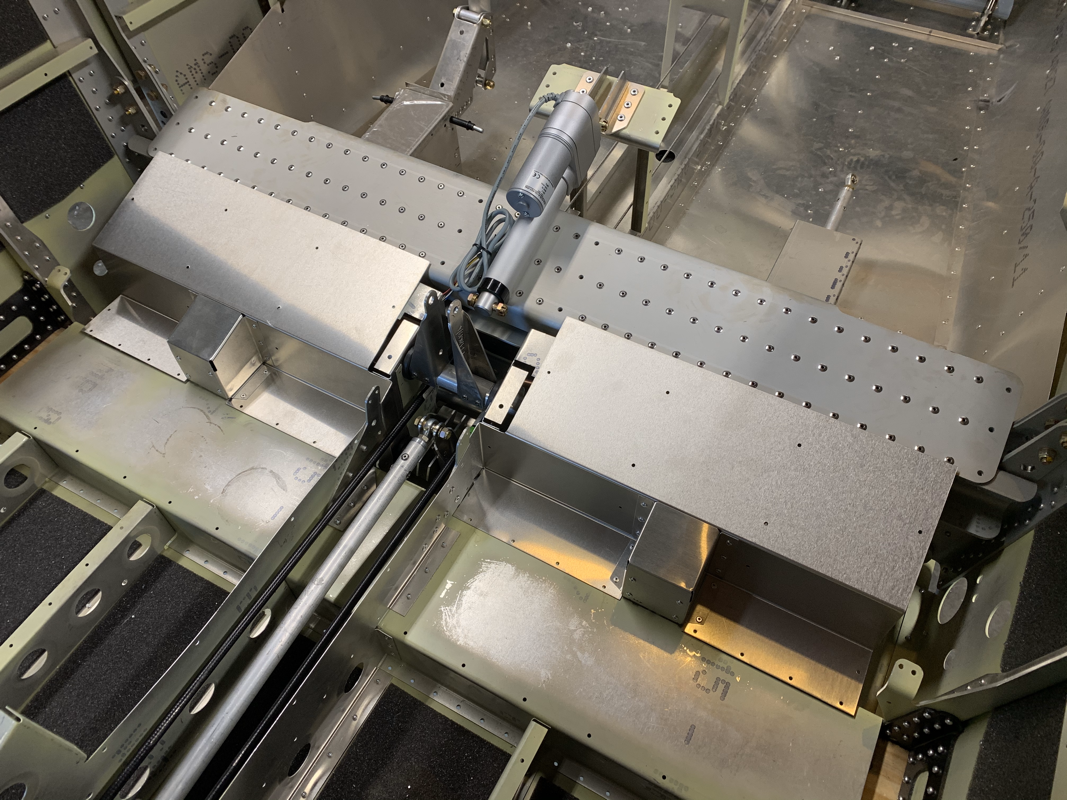
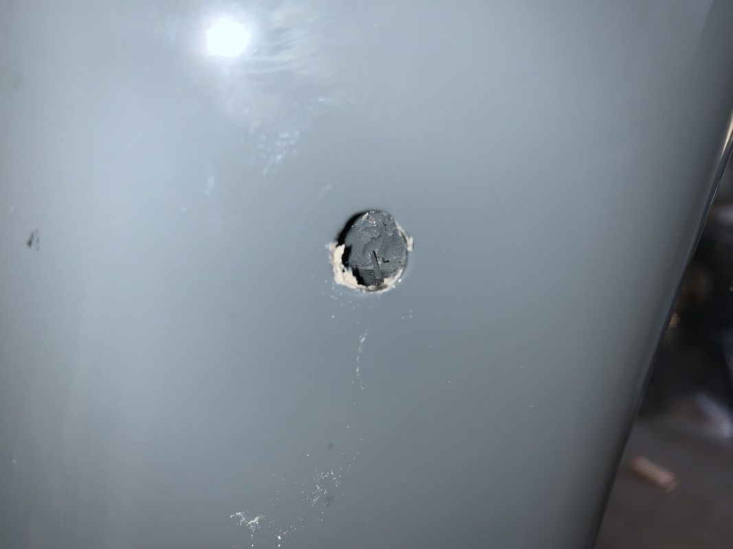
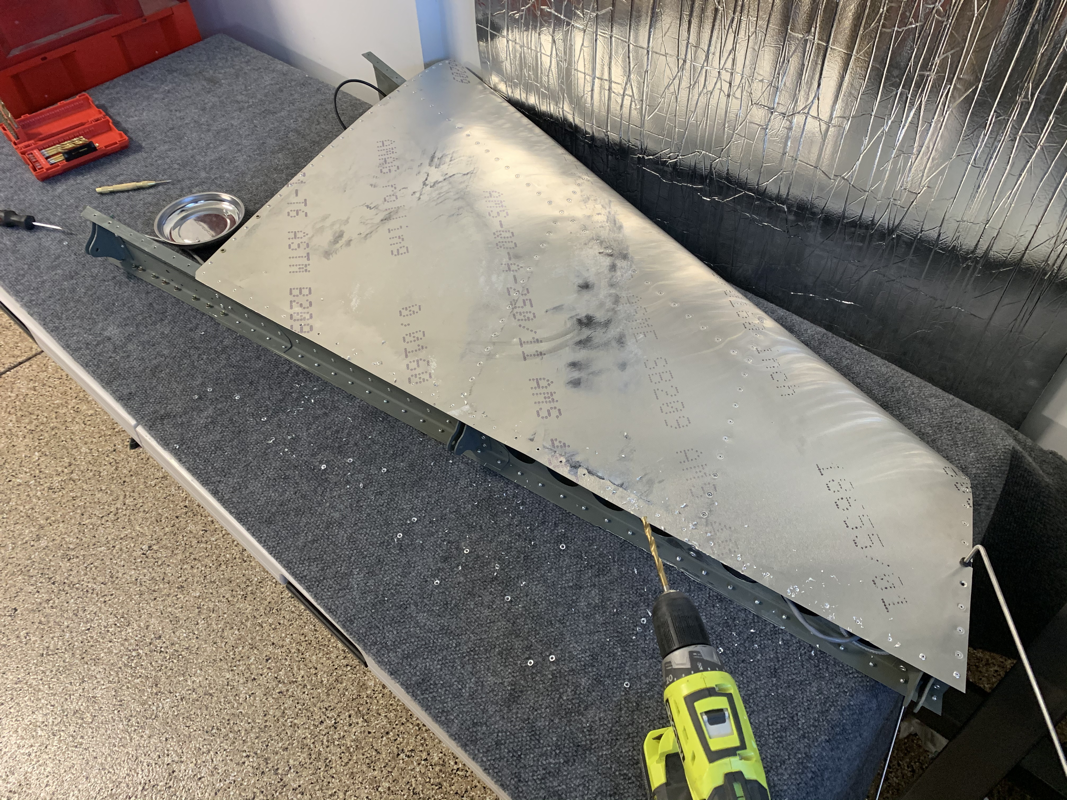
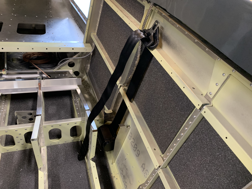
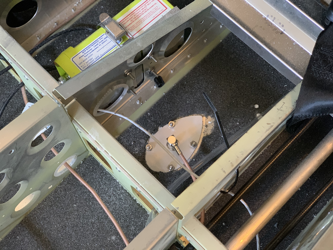
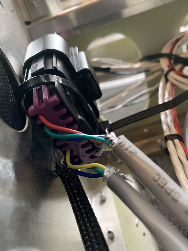
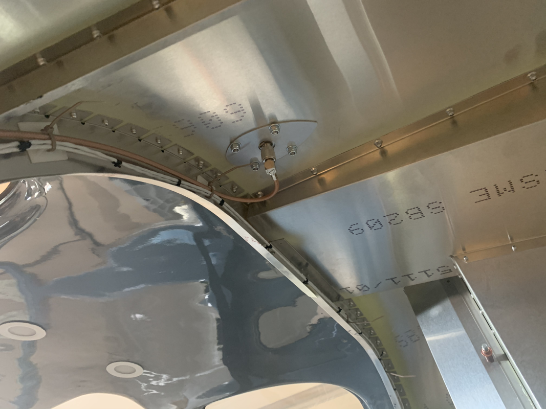
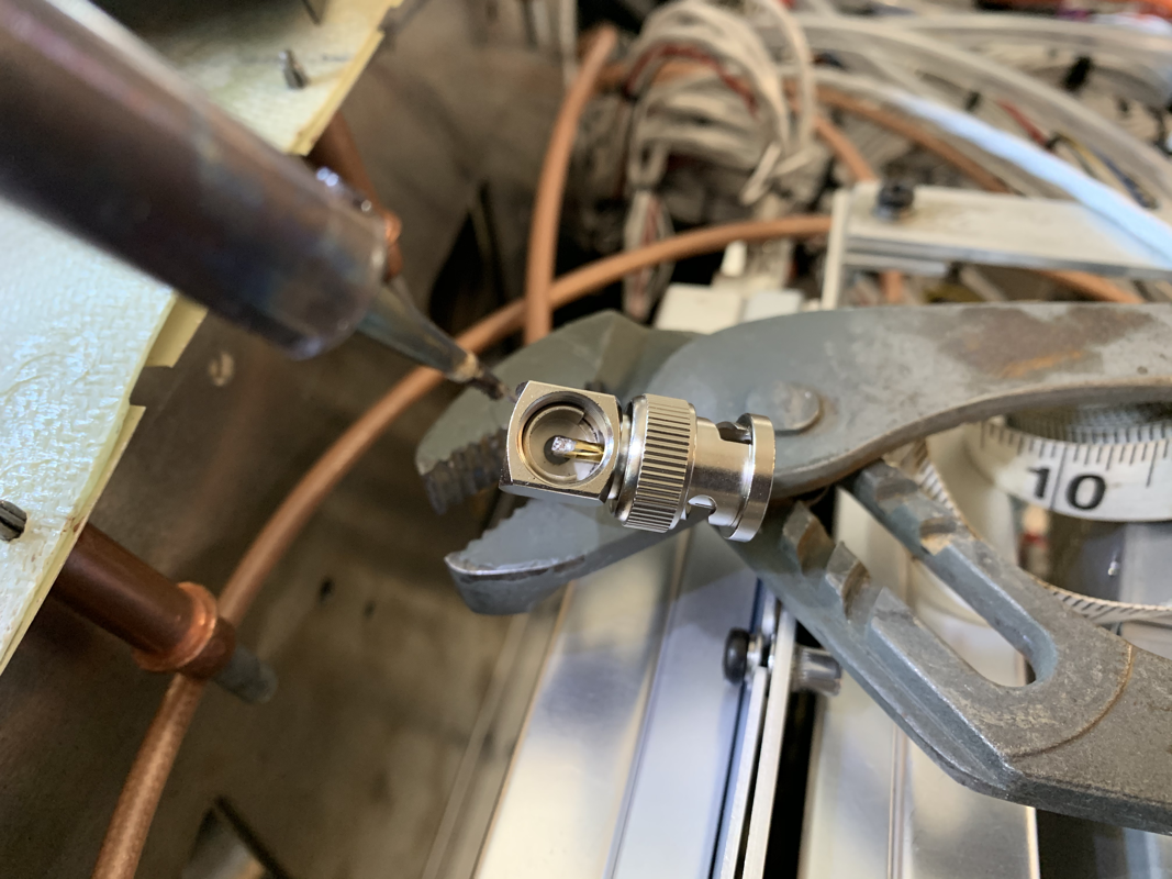
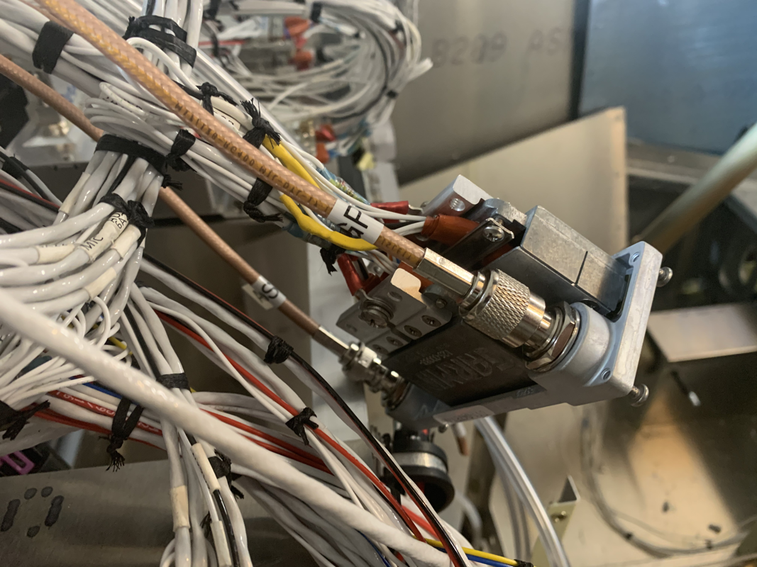
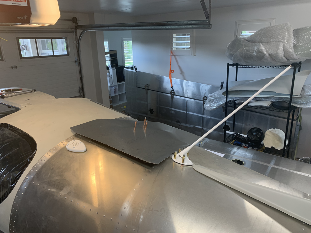
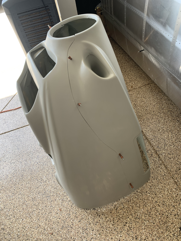
So I had to figure out how to best fit the VOR Antenna and run the wire through the ribs since the instructions only account for a Tail Position Light OR a VOR Antenna. This is to ensure there is no electromagnetic interference of the VOR Antenna. However, with the low power requirements of modern LED lights make this a bit less concerning, so I opted to do both. In order to accommodate the second wire running through, I drilled a hole on the top rib and put a rubber grommet through. From there, I could keep the wires separated on the front and back of the VS. From there, I was able to prime and apply the skin to the ribs, cleco in place and check the alignment. Straight as an arrow, so I began riveting one side. I checked alignment again and was still good, so proceeded to finish up. It was a bit tricky fitting the VOR Antenna. The antenna base is a bit tight against the rib, and it did cause a bit of a bump around the antenna on the skin. I don’t see that being a huge issue really. I did have to shorten 2 rivets to fit near the antenna. Glad to be done with the Empennage Kit! Now, I await the arrival of the QuickBuild Kit expected in mid to late October. Until then, my wife gets custody of the garage. ;-) I was able to spend some time finishing up the rudder. The main hurdles that took time were fitting the rudder tip and placing the VOR Antenna on the top rib of the Vertical Stabilizer. Placing the light was pretty straightforward, but when I went to fit the rudder tip, it was a bit too long. I asked Phillip how he went about it and he said to just trim the back a bit to get a snug fit. After that, it was just match drilling the holes and countersinking the first 7 holes. I saw a note in Phillips blog to pay careful attention to the number of countersink holes since the instructions say do the first 9, but there are only 7 done on the skins. Once things all lined up, I went ahead and soldered the light wires and wrapped them with heat shrink. I added some wire protection to the part of the cable that is exposed outside of the skins. I did need to use the angled pop rivet tool on the bottom of the rudder, as it was pretty close quarters to the plate. I did a final check of the alignment and it was still straight. Feeling good to be almost done with the Empennage! Now to skin the Vertical Stabilizer to finish things up! I received word that my QuickBuild Kit has shipped from South Africa and is on it's way! Woo!
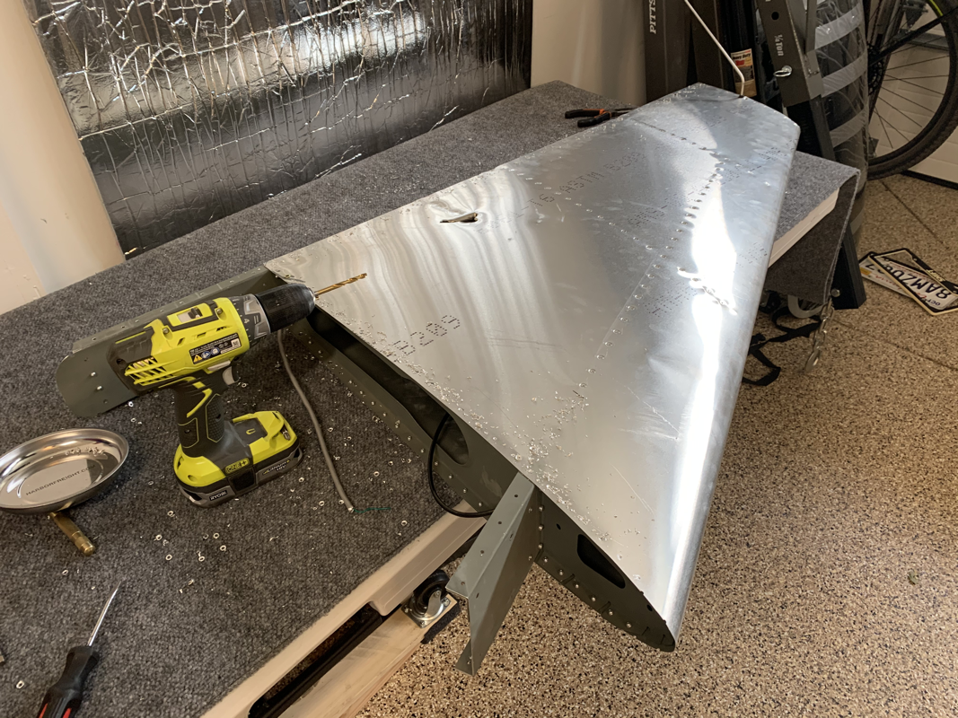
While working on the Empennage has been satisfying, I am really excited to finally be able to actually sit in the fuselage and make airplane noises. ;-) I'm sure I'll be able to finish up the Empennage soon, so there will be a bit of down time during the 40+ day journey to the United States. I received the new set of rivets from Perry at The Airplane Factory in Torrance, CA and was able to continue putting the ribs together. I also worked on trimming the flange to better fit the bottom rib of the rudder. No more interference! I'm starting to skin both parts and check if there are any alignment issues, so far so good! Now I'm going to break out the soldering iron and connect the wires to the Anti-Collision/Beacon light on the rudder. I went with the Aveo Engineering Minimax Ariel. Since this is a permanent connection, I'll be using heat shrink sleeves to protect the connections. I will also be installing the VOR antenna in the Vertical Stabilizer. I see the manual recommends that you don't install both due to possible interference, but with the low voltage of modern LED's I don't see that being an issue. I also see that Phillip went the same route with his Sling TSi build. This time I did the cleaning, scuffing, degreasing and priming of the Vertical Stabilizer and Ruder in a batch. This seemed to speed things up since I already had everything prepared and lined up to use. I just had to make sure the parts were different enough that I could tell what goes where when it comes time to assemble it all! I did notice that the flange at the bottom of the rudder (Last Photo) does rub against the rib. It causes it to expand, leaving the skin to be uneven and would probably be an issue. Mike Black from Sling Central had also mentioned this issue and came up with a slight modification that seemed to work well and doesn't affect the structural integrity, so I'll be making the same fix. Overall, these parts are coming together a lot more quickly than the Horizontal Stabilizer and Elevator. Progress! Until, I ran out of 4mm x 10mm rivets. I'm also looking to be a bit short on the 3.2mm x 8mm rivets.. Perry from The Airplane Factory in Torrance, CA is sending some over and will pick things up from there. |
Archives
September 2021
Categories
All
|


 RSS Feed
