|
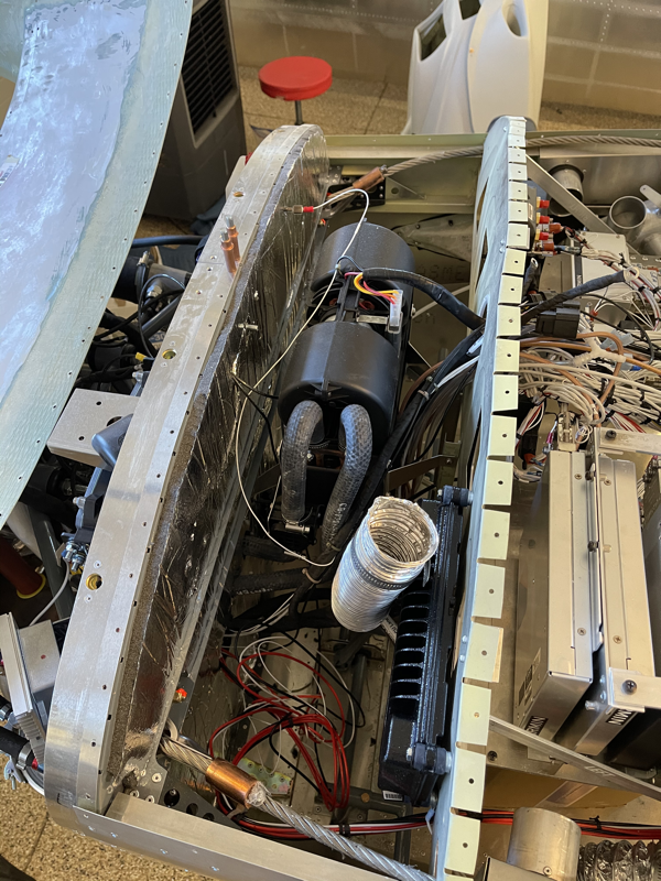
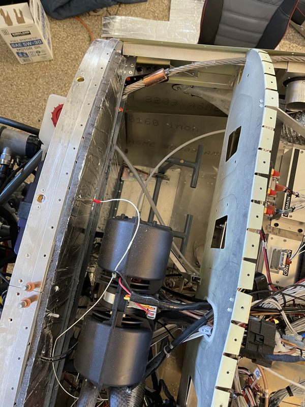
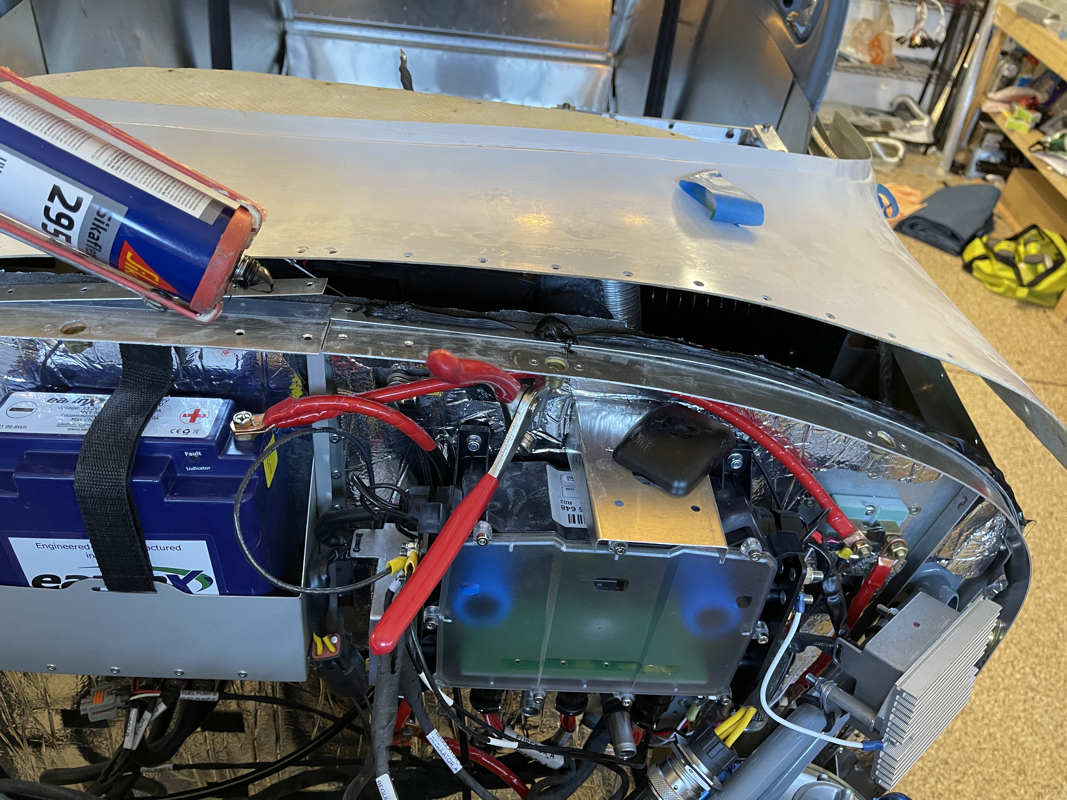
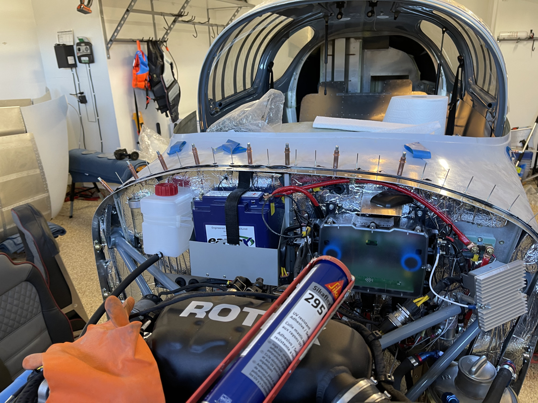
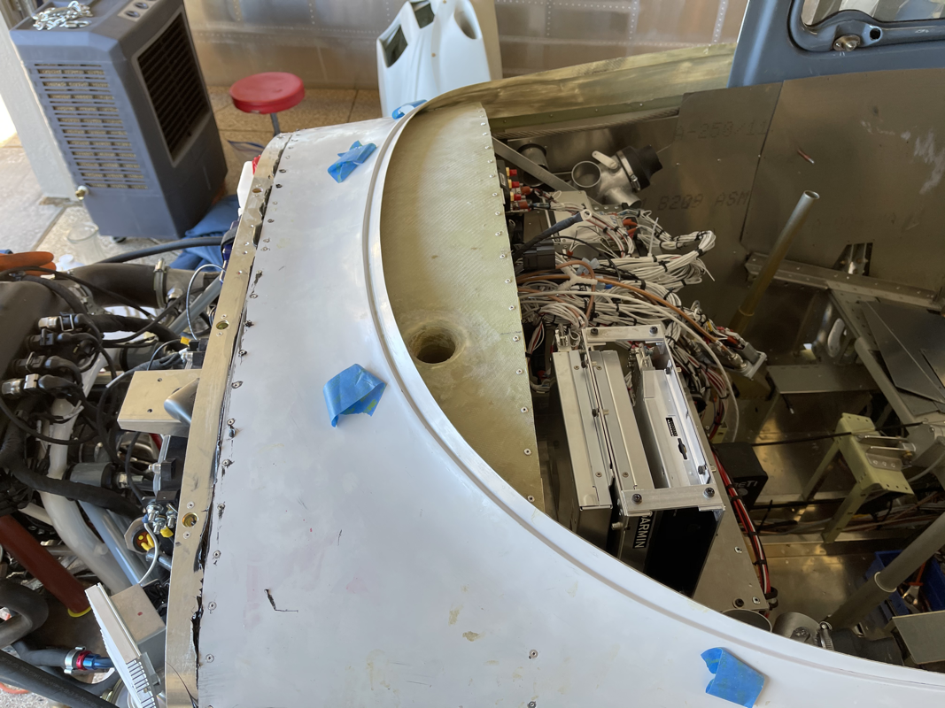
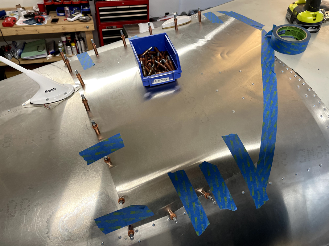
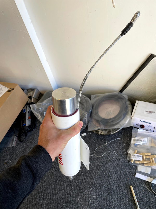
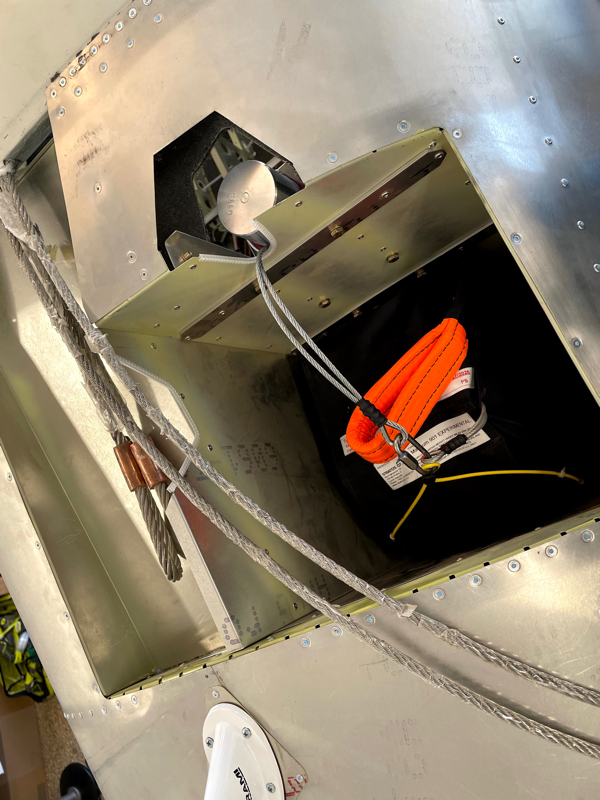
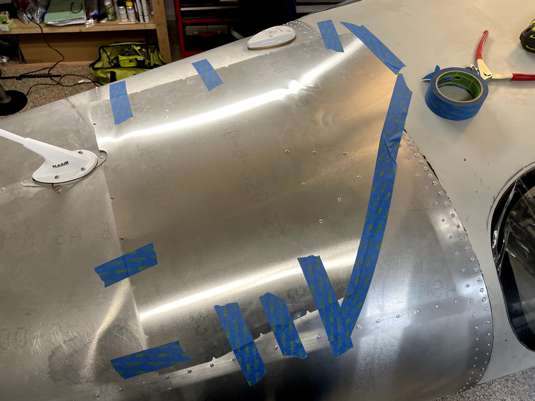
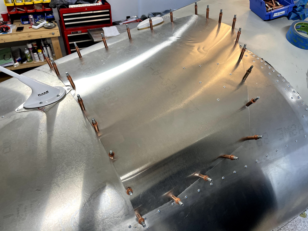
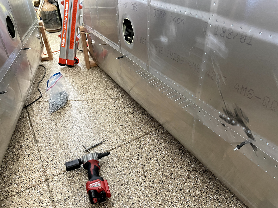
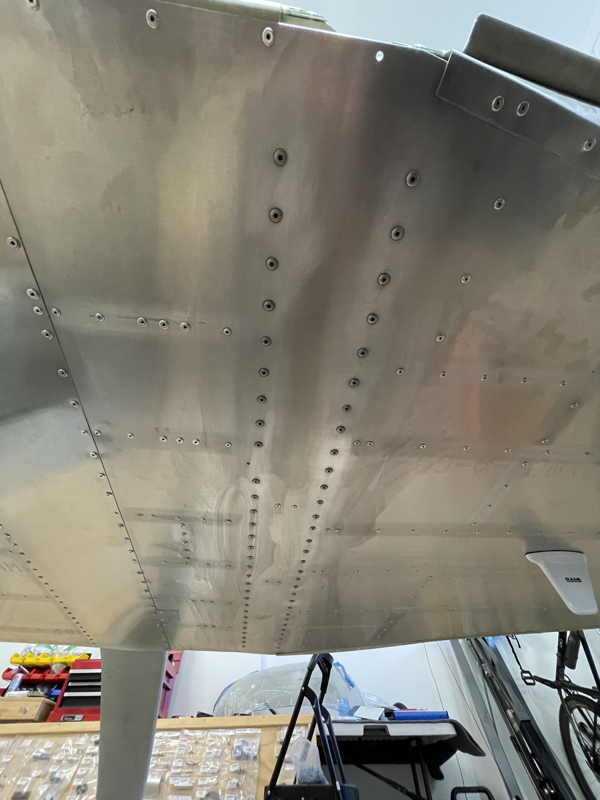
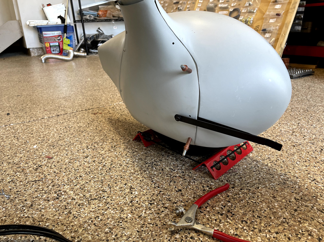
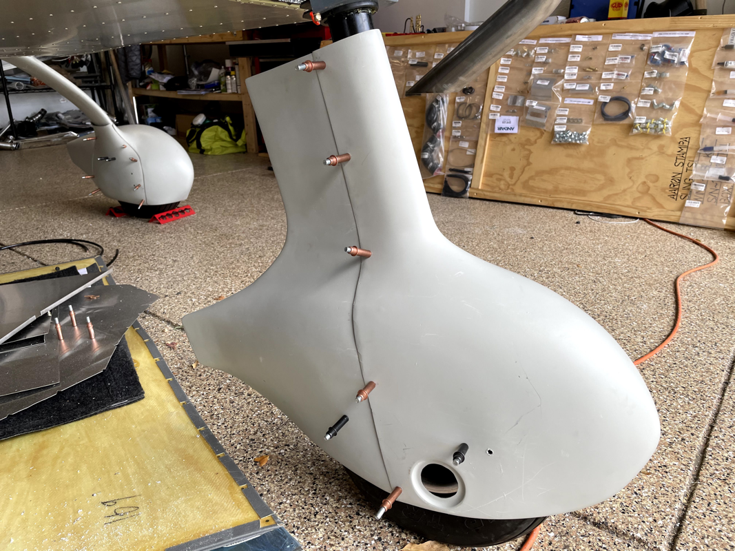
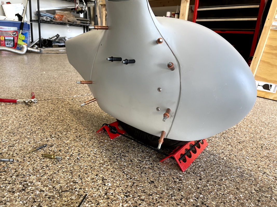
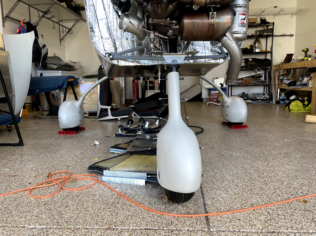
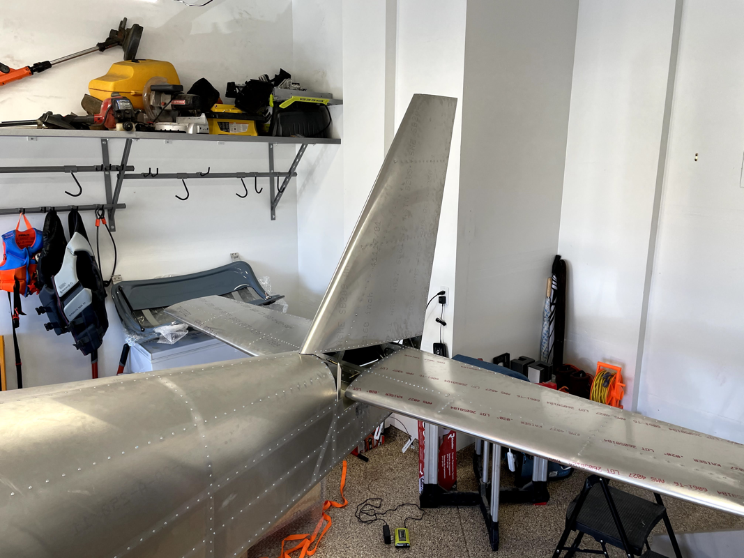
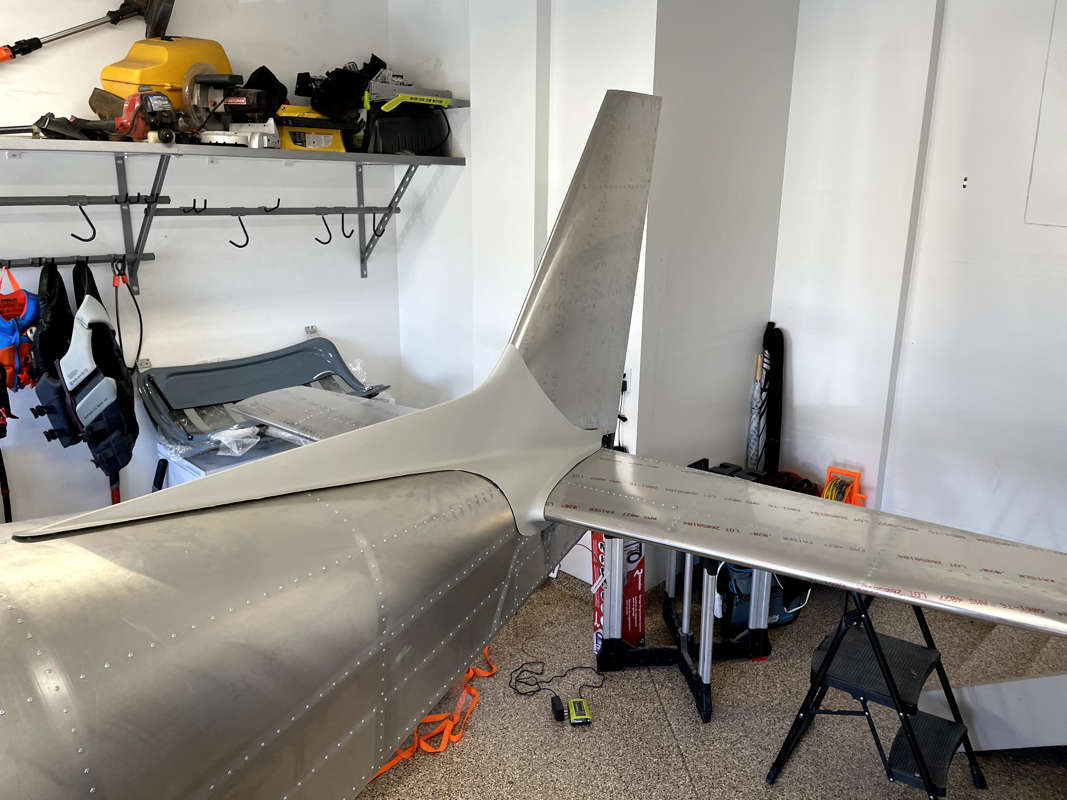
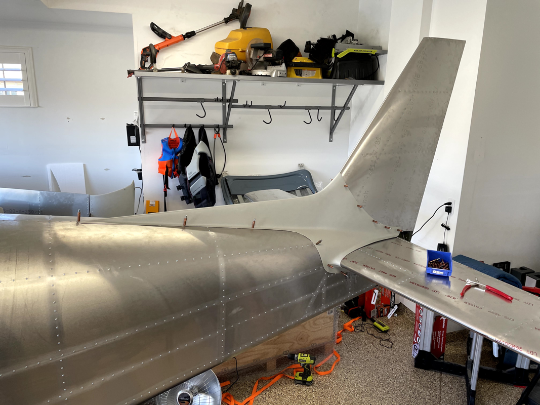
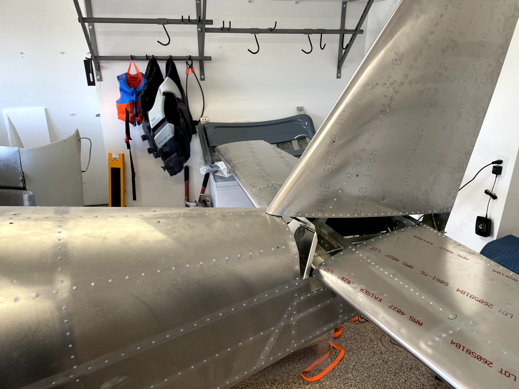
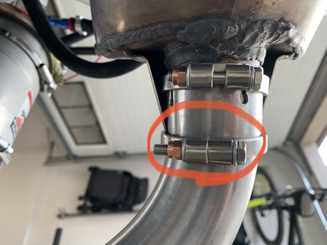
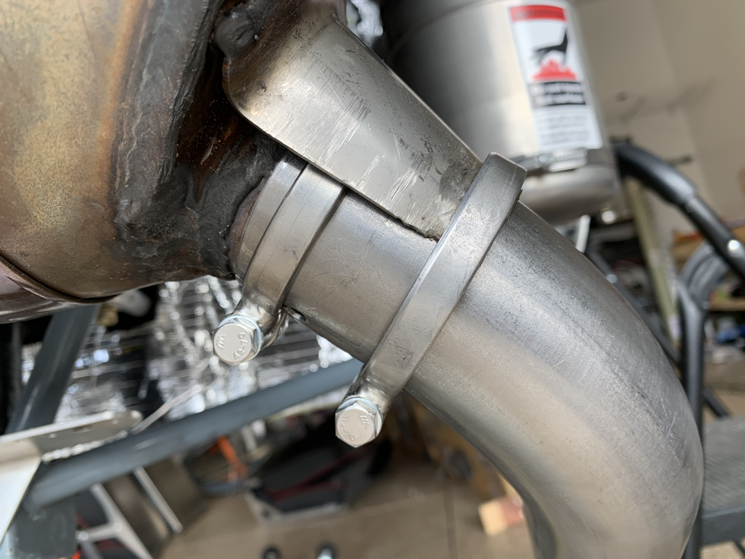
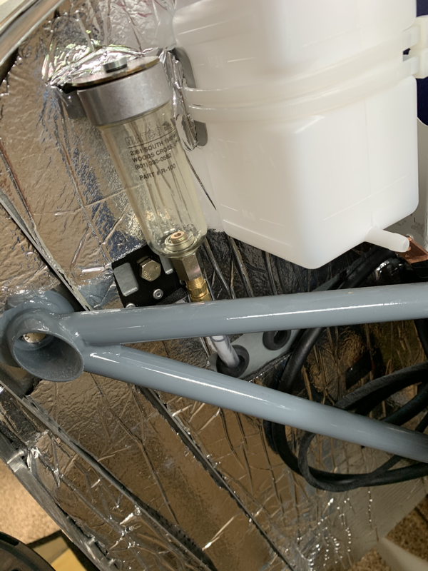
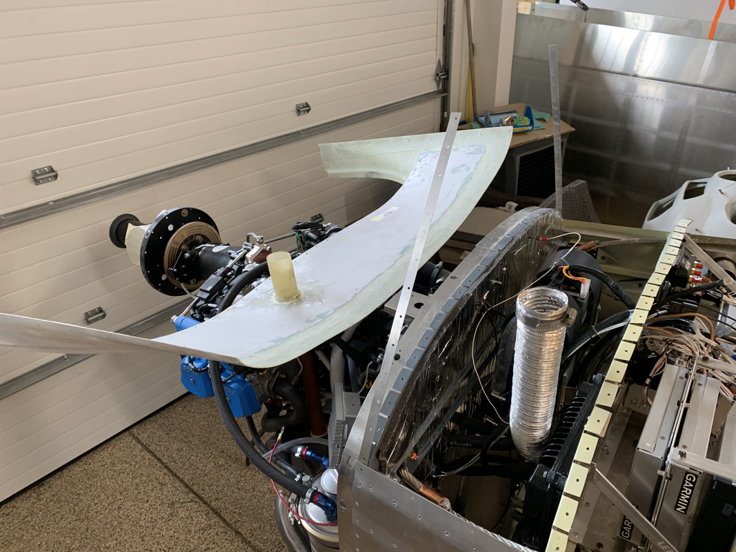
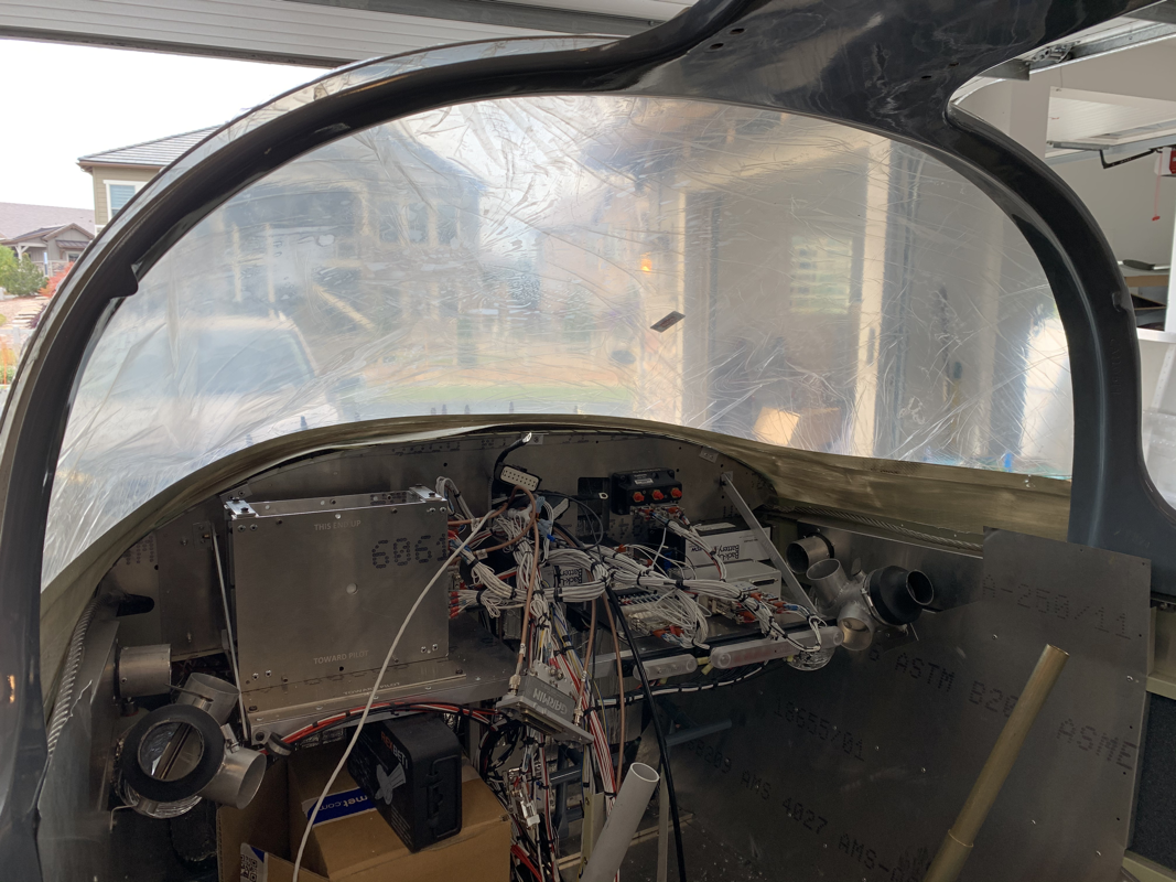
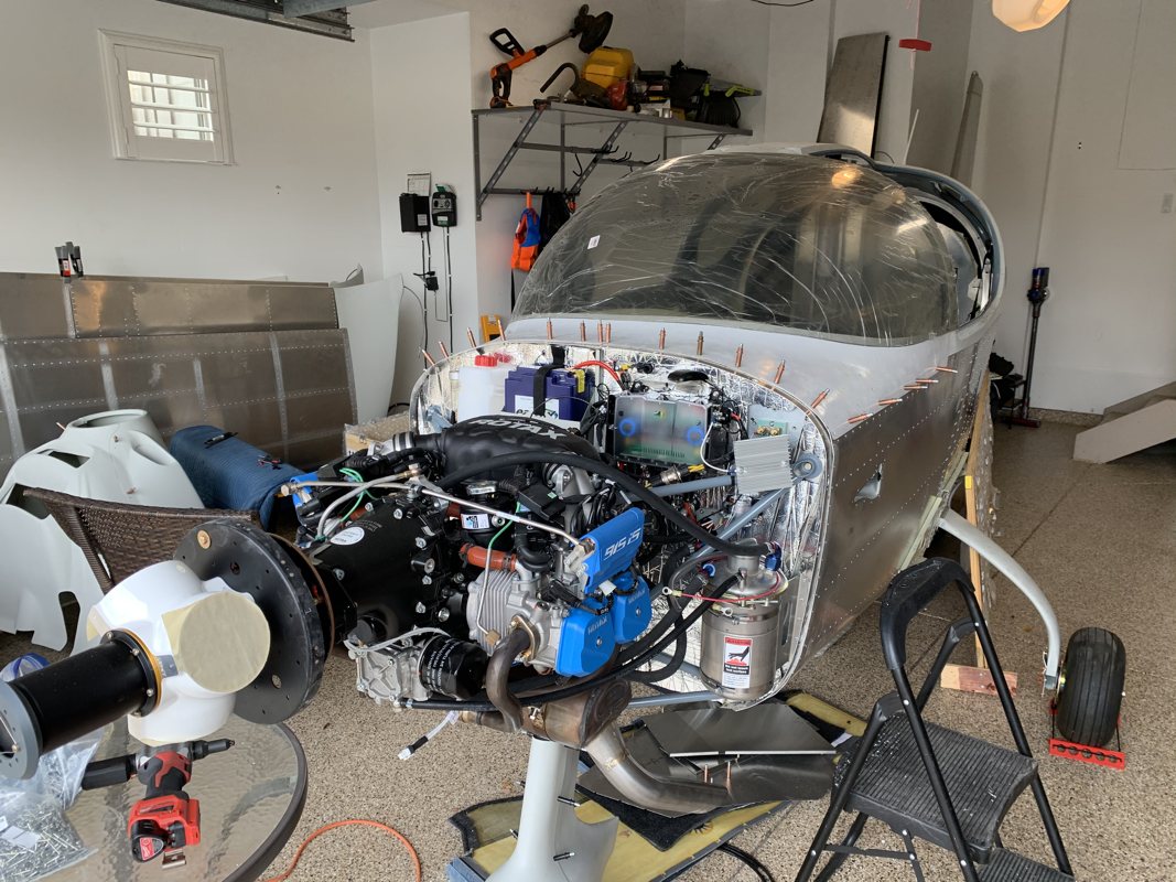
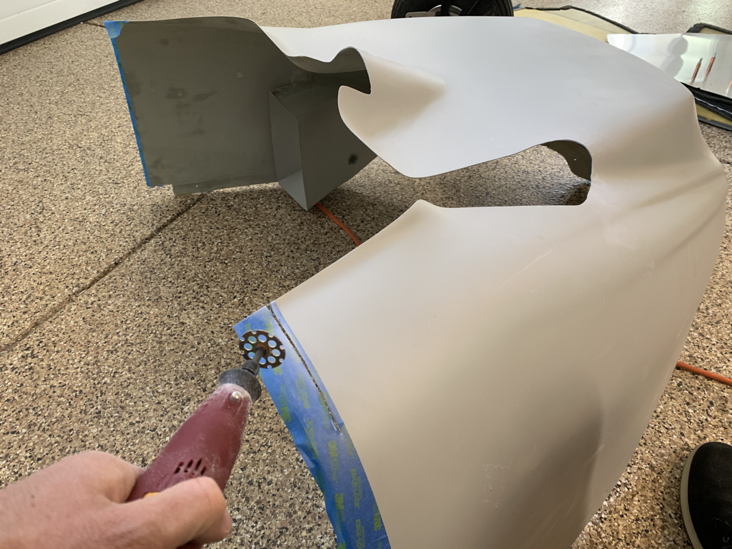
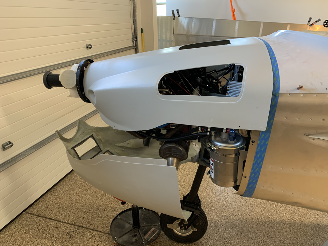
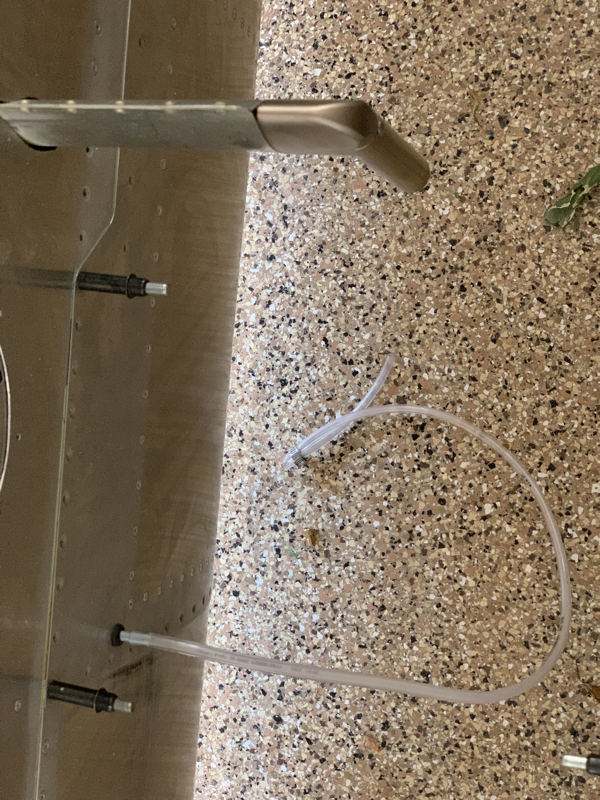
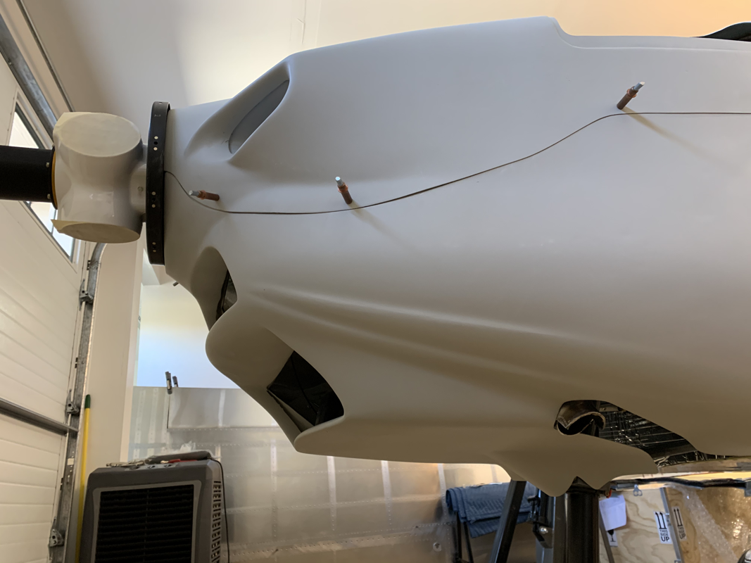
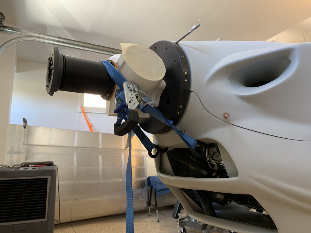
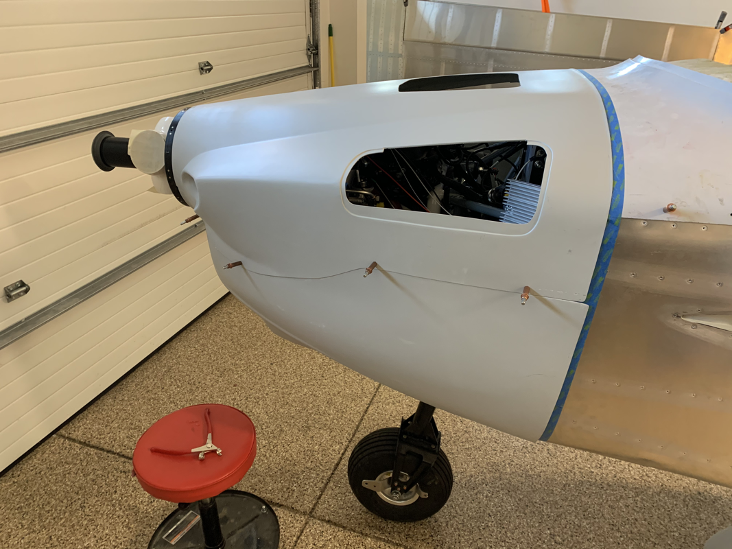
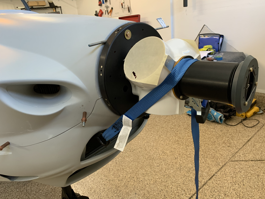
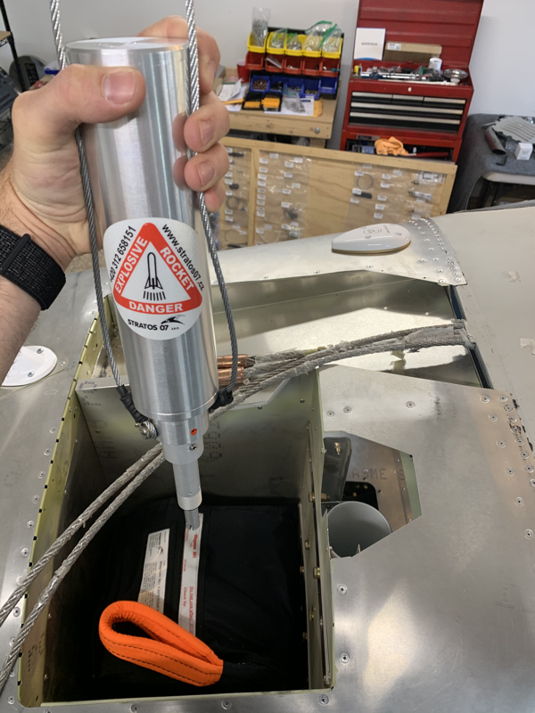
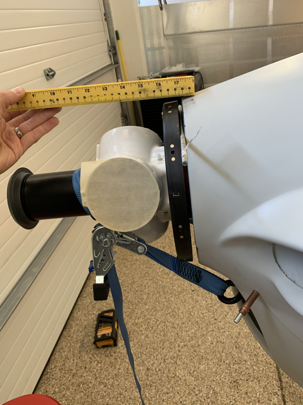
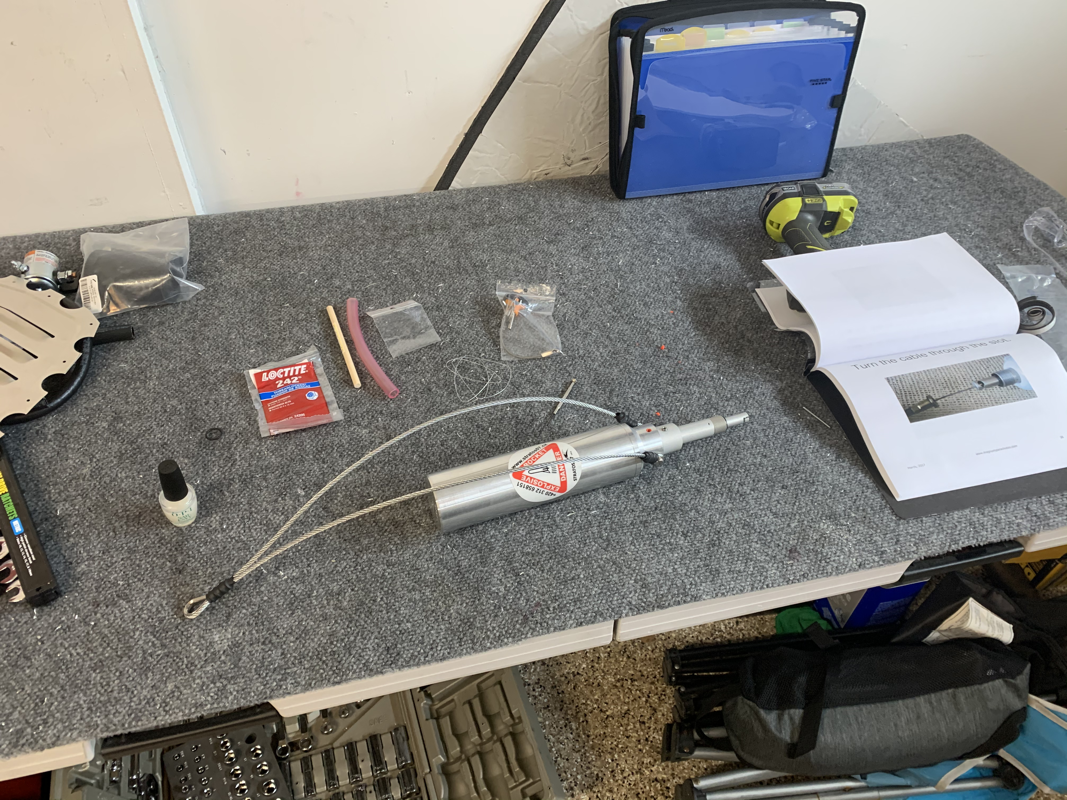
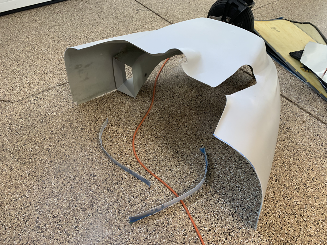
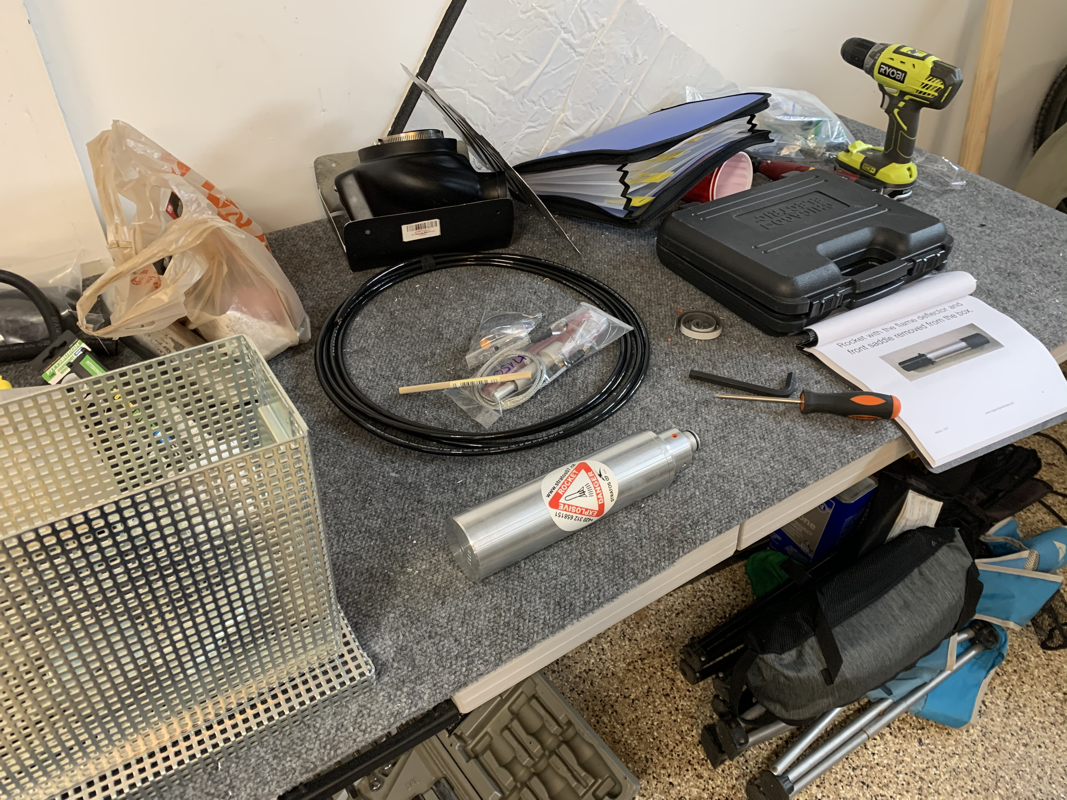
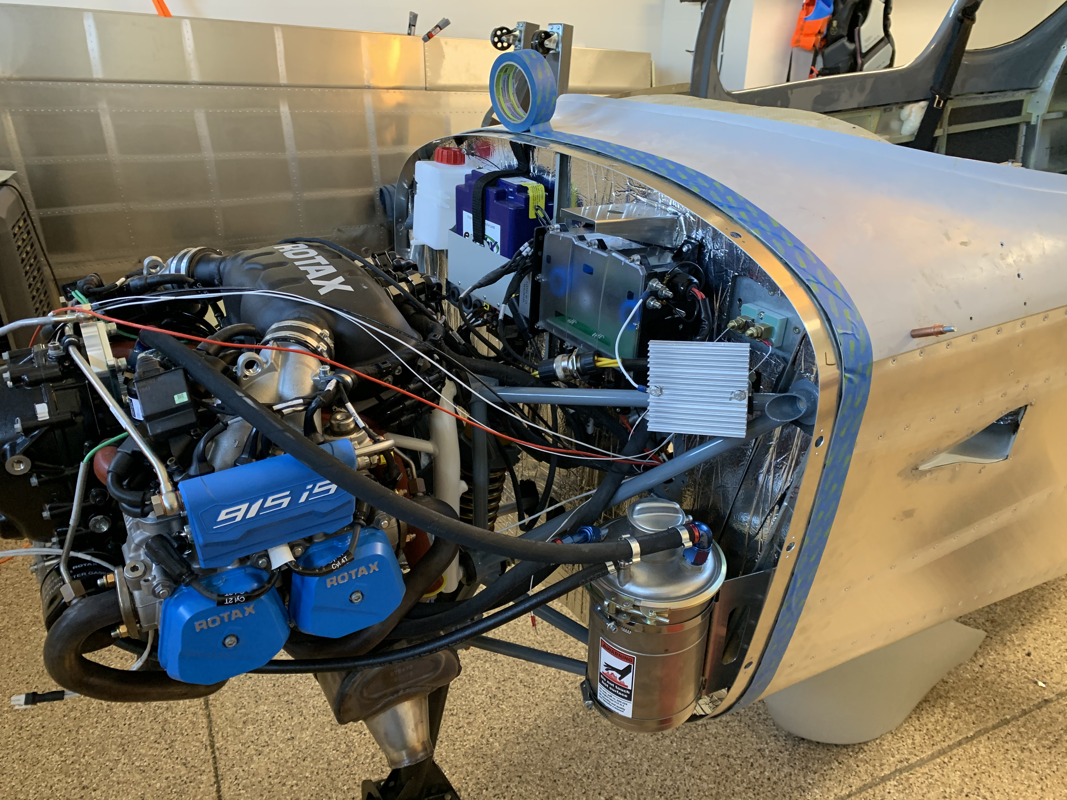
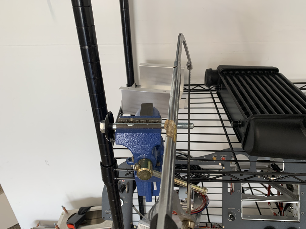
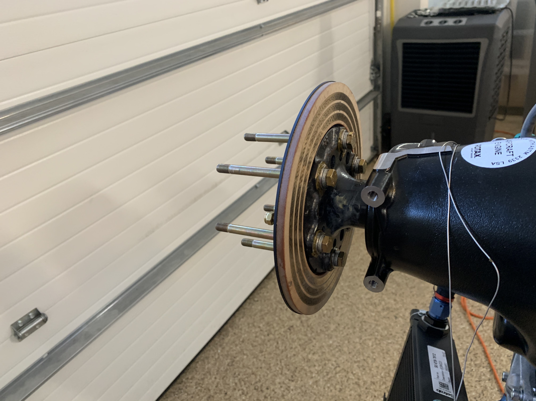
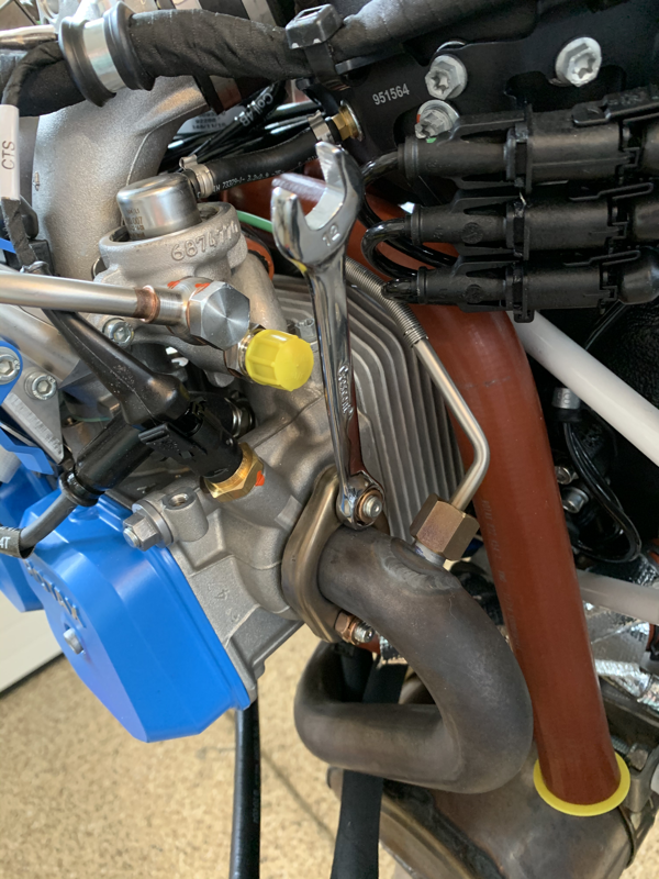
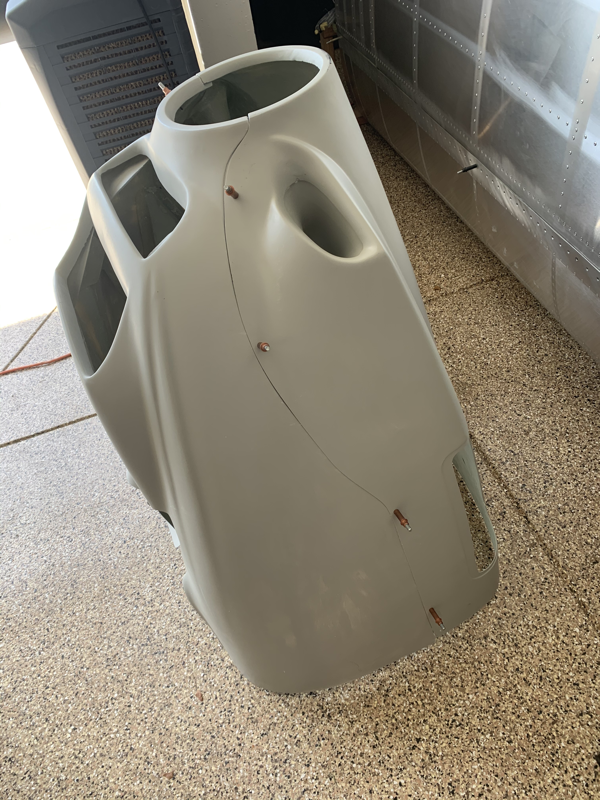
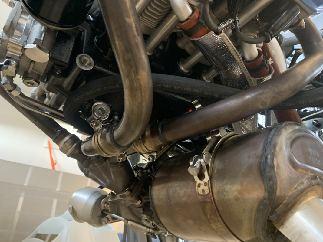
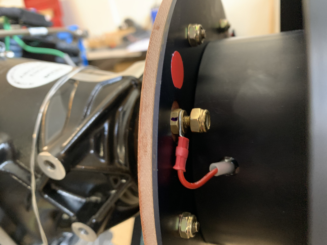
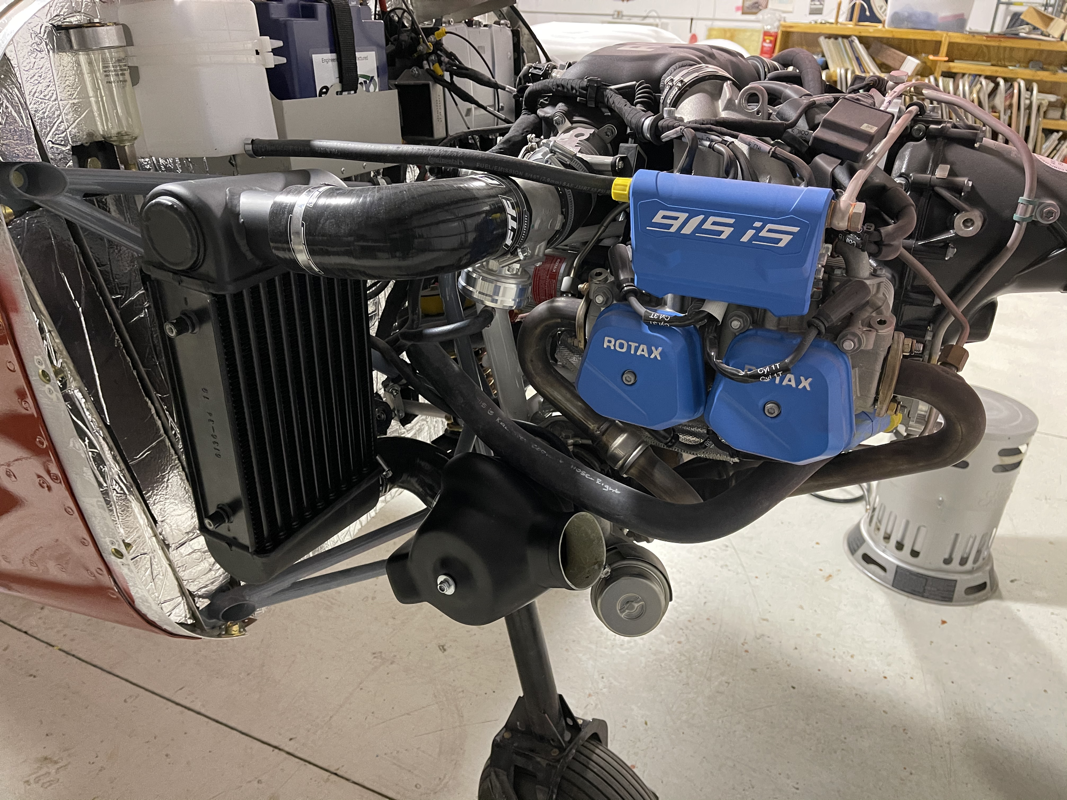
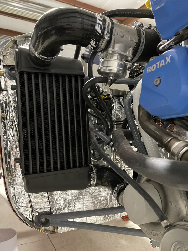
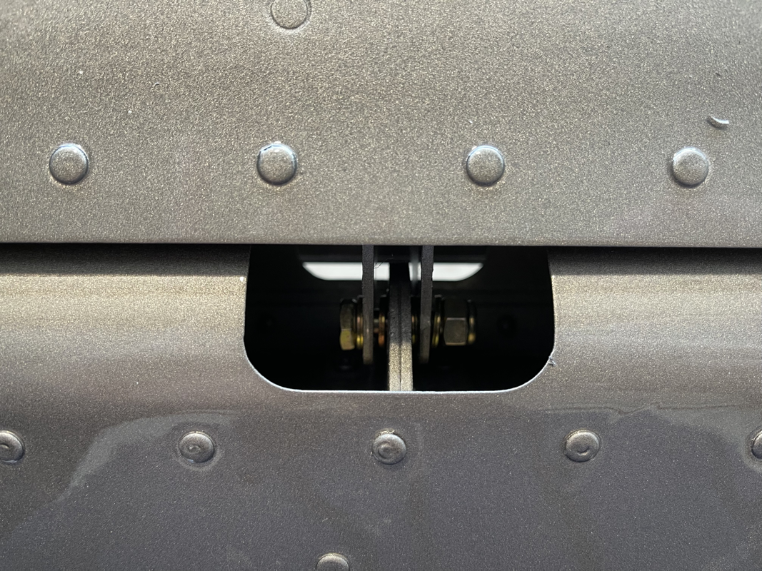
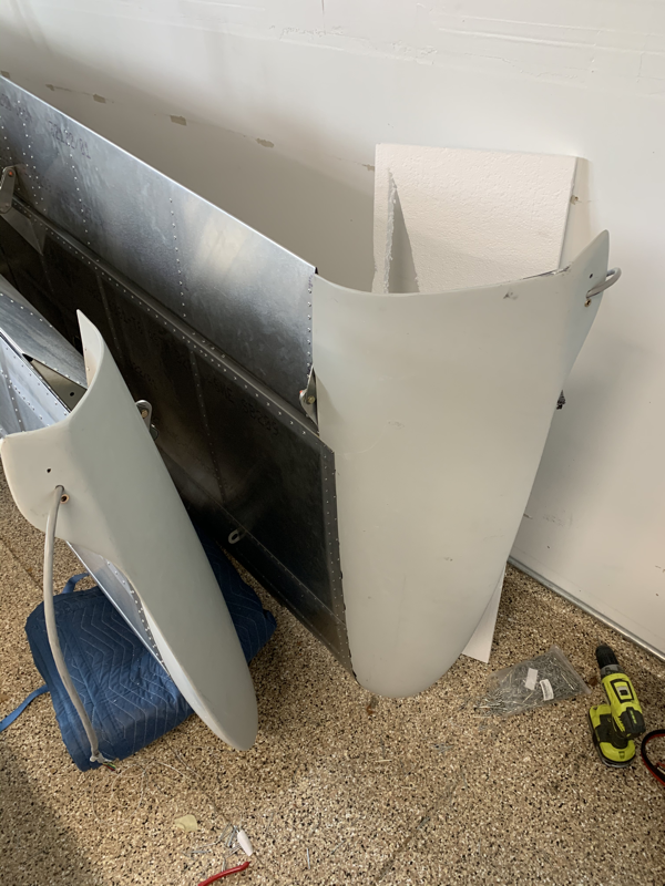
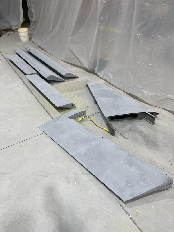
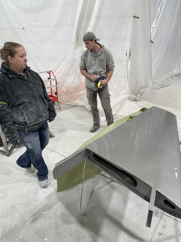
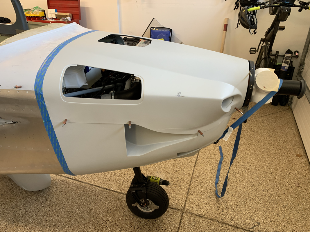
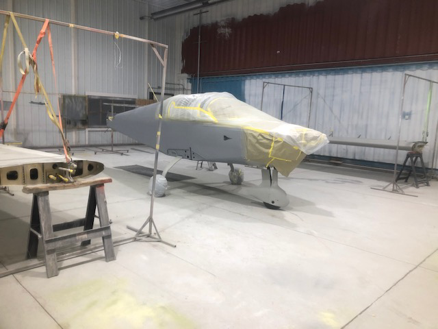
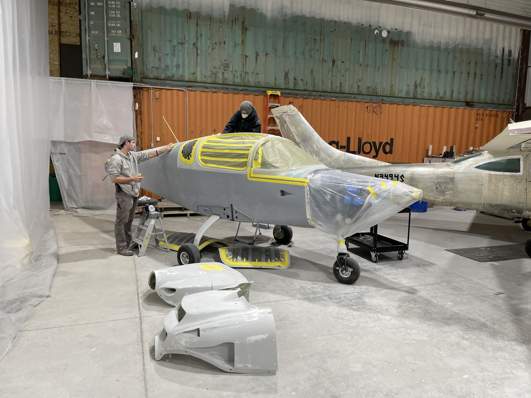
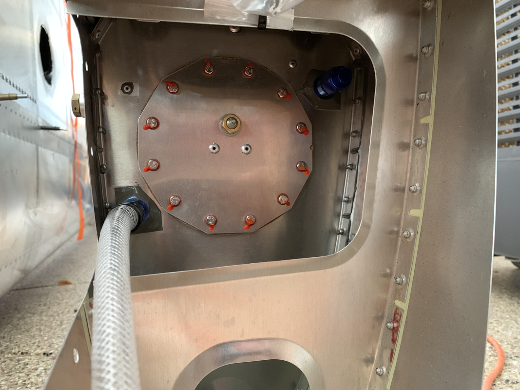
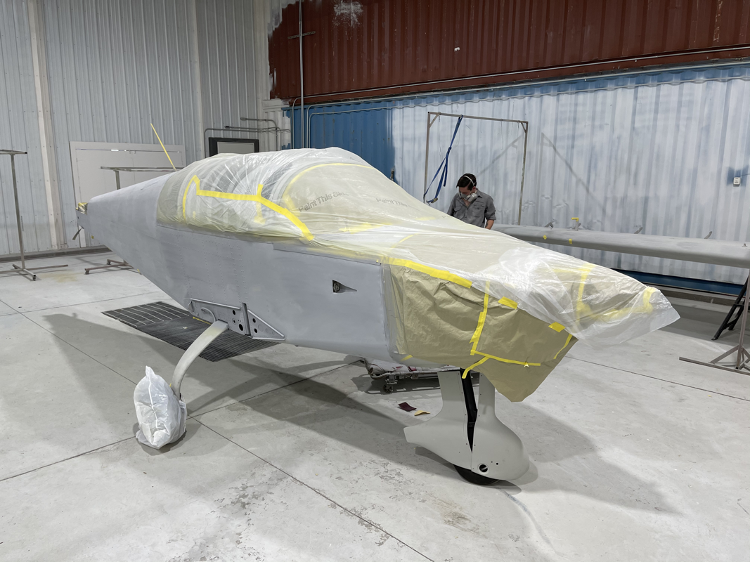
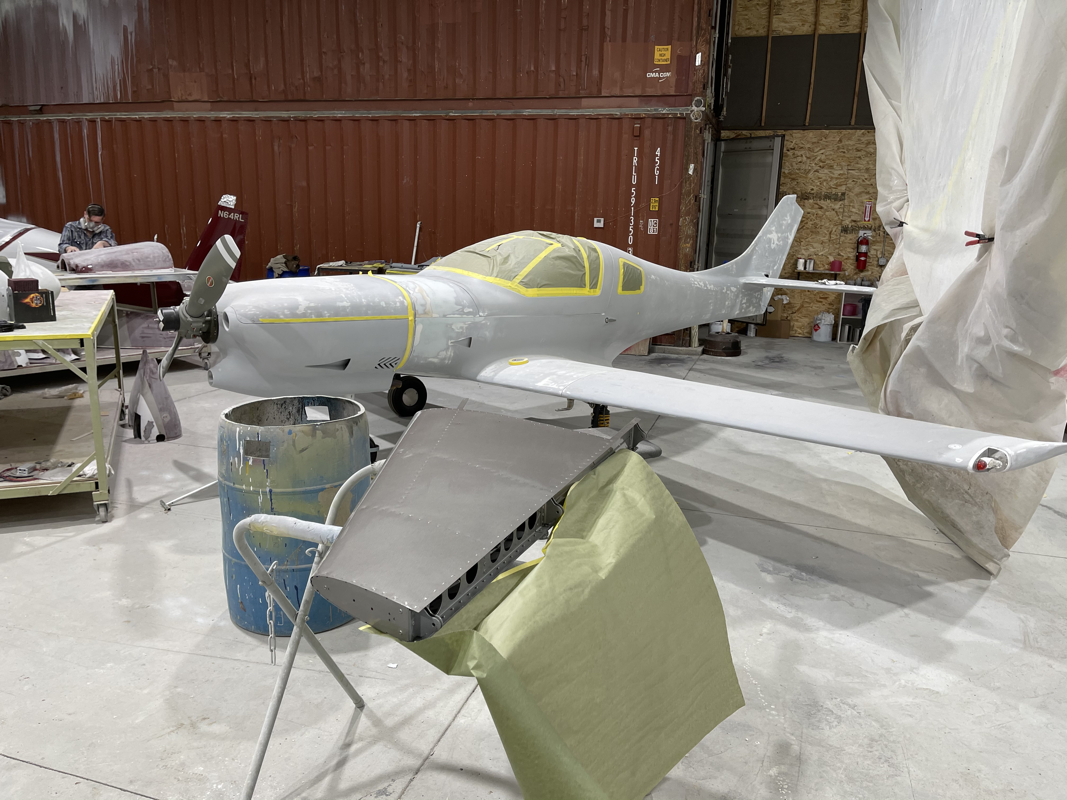
Documented the process of bonding the windshield: - taping / masking fuselage - taping / masking windshield - bonding and applying contact pressure - dash vent tweak - Aveo 2” Maxi Vent.. I’ll be running the outside air directly to these. Heat will be routed to the front floor and through the side channels. Here’s the latest update from the last week or so.. - Routed the fuel lines in the fuselage - Tidy’d up the fuel lines with some zip tie and fuel line stand offs - Spliced an extended the fuel pump wire, it was too short to reach around to the other side of the pump - Added heat shield to the oil lines - Trimmed the windshield to fit and get ready for bonding In order to fit the windshield, I need to get the front fuselage cover on. Since it's just held on by rivets, I could imagine some water getting pushed through this section, so I decided to add sikaflex for a solid seal. It's messy, but worth it. I did have some trouble fitting the parachute rocket all the way in since the cables that connect to the bottom of the rocket push on the housing. The trigger doesn't line up through the hole on the bottom. I gave up trying to do it while attached to the plane, so I took off the rocket housing and was able to fit the rocket easier. Scary nonetheless handling a live rocket. Glad that's done! I lined up the parachute blast skin and drilled the holes into the fuselage and canopy. The factory recommends that you use some PVA release agent and apply some clear silicone underneath the skin to prevent water seepage. Just doing some final riveting on the wings, attaching the fuel tanks since they passed the pressure test. I was going to do the Service Bulletin 14 - replacing the aluminum rivets with stainless steel ones on the spar carry through, but it seems that the factory already did that for me in my quickbuild. Note the darker rivets with rounded edges compared to the same size rivets nearby. Continuing my exterior component adventure, I decided to focus on fitting the wheel paints and the tail cover. The hole finder came in handy for this exercise. I've seen quite a few different ways, but this seemed the most logical and I didn't have to 'redrill' any missed holes! The tail cover was straight forward, just line it up flush against the vertical and horizontal stabilizers and drill.. fill with rivnuts. I am working to finish up the firewall forward electrical and any final placement of the wires that will be covered once I put the front fiberglass piece on. I had to reroute some of the heater ducting and also remembered to attach the heater control cable. I also routed the brake line through the firewall forward gromet. One thing to note, and I've heard about this from another builder, the bottom muffler bracket that mounts over the muffler shroud is a manufactured incorrectly - it's a bit too big. The fix is to shave off some of the metal where the bolt joins them, maybe a quarter inch total. It didn't take too long with a grinder and it fit just fine afterwards. This week I focused on getting most the antennas installed and wiring up all the connections. I installed the Comm1 Antenna on top and made the RG-400 BNC connection. I then test fit the parachute skin and it looks like that may be a tight fit. Will have to make sure I figure out where that goes before I fully secure the antenna. Additionally, I’ll need to put in some rivnuts there since there’s no access to the bottom of the antenna. I then installed Comm2 on the belly between the ELT and center channel. The antennas come with hole templates for mounting, so it was pretty simple to drill through to size. The Transponder / ADS-B antenna was a bit more difficult to mount. They have a hole pre-drilled on the center bottom of the fuselage, but with the inside skin, it took a bit of work to create holes for access to the mounting screws. I used a 1/2 inch drill bit on the inside skin to get it big enough for a socket wrench to fit and secure the bolts. I then turned my attention to figuring out the wiring diagrams and crimping the pins for the Delphi connectors. Took a bit to get into the rhythm, but eventually figured out how to crimp without the right crimper - I had a molex crimper and apparently these type of pins require a bit more expensive tool. The Molex crimper worked, but it took about 4x the time. I finished up the canopy wiring and installed the lights. The front ones were easy since I just had to mount them with 3 screws each. The back lights took a bit more work since I had to enlarge the hole and clear some styrofoam to give it a flush fit. Since my pilot light dimmer is on the panel, I now have an extra hole in the canopy I get to work with. I figure I install some sort of power source for a GoPro camera, so I spliced the power from the rear lights and ran some wires there. I was able to order my battery! I decided to go Lithuim since the weight savings is pretty drastic. The Rotax 915 requires a battery with at least 350 cold cranking amps. The ETX900 battery fit the bill with 400 CCA’s and only 4.9 lbs! Bonus, I was able to get the 10% AirVenture discount. Good timing! I decided I might as well get to doing Service Bulletin 17, which has me replace the aluminum rivets in the elevator control stops to stainless steel. To do so, I had to remove the ribs in the center console that hold down the elevator torque tube. After that, drilling the rivets out was easy with a flexible 90 degree drill bit. The service bulletin didn't specifically specify, but I decided to use some anti-corrosive on the stainless steel rivets since it will be in contact with a dissimilar metal. I was not fully satisfied with the stiffness of my elevator and wanted to make sure it was butter smooth this time. While I had the elevator ribs out, I decided to give them a good shaving around the area that holds the torque tube bushing with a dremel. I tried fitting a few times and sanded a bit more. I finally got it to where there's zero resistance! Definitely happy I got that resolved. Before you install the side panels, the factory suggests using some high density foam to block open areas in the rear passenger air channel. I couldn't find any decent foam blocks, so I decided to get some polyurethane based foam. It did the trick and shaving it to size was easy with a hand saw. Next I moved on to starting to wire up the canopy for the front and rear lights. There's a tube that routes from the back left of the cockpit through the canopy and exits in the center between all the light holes. Not too easy to see in there, so I used a wireless borescope to understand what I'm working with. I had to punch some holes through the styrofoam in the canopy to get the wires through to the front pilot light areas. The rear passenger lights were easy since the tubing routes by the hole. I'll put on a protective sleeve on the wires that exit the canopy and route them below the rear seat for connection to the harness. I was really excited to get the avionics mounted and wired up. It would also let me know the proper placement of the wiring harness so I can secure the harness to the fuselage’s channels with zip ties. I did have to get some angled aluminum from Home Depot to help secure the doubler plate on the back to the rib flange, but that was the only item that required a bit of work. It took me all of 20 minutes to wire up all the avionics on deck! Can’t thank the guys at MidWest Panel Builders enough for their work on the harness! It is a few steps ahead, but I wanted to see how it looked with the upholstered dash and the avionics panel. Looking good! I’ll be taking those off so I can do the firewall forward kit and engine.. expected to arrive in September. Until then, I’ll make sure all the wires and pitot static lines are secured in the channels. I already started with the passenger headphone jacks. The sticky square zip tie things come in handy! Just stick it on and run the zip tie through the channel. I’ll also be working on some of the Service Bulletins that came out for the wing spar rivets and the elevator stops and replace the aluminum rivets with some stronger stainless steel rivets. It's been a while since I was able to work on the plane with summer vacation, family visiting etc... So I was happy to get my hands dirty again. I drilled a hole for the outside air temperature sensor on the pilot side air scoop. It's good to get this done before you mess with trying to mount the avionics panel, as things get pretty tight. The modular panel rack system that MidWest Panel Builders provided requires that the top fiberglass skin be on to provide adequate support of the 'panel' rib. So I went ahead and used my nifty hole finder tool. Just plug it in the rivet hole and place the drill on the other end and viola! I couldn't imagine trying to get those holes aligned blindly. I'd highly recommend them! The only remaining metal pieces I have are the cowling strips that connect the fuselage and the cowling. It is a bit difficult to figure out exactly how they are placed based on the instructions, so hoping the close up pictures help others. It took me reaching out to a fellow builder to stop scratching my head! You take one skinny strip and one larger strip and line them up. The side with an angle will be at the bottom of the fuselage, the flat end on top. You then have to dimple the first 18 holes in each for the countersunk rivets on the fuselage. Make sure to fit the pieces to the frame before and label which side is which first - they only fit one way. You don't want to end up with a strip with dimples the wrong direction (almost made that mistake). From there, you'll fit the skinny strip between the outer fuselage skin and the firewall flanges. I used a rubber mallet to assist getting that in there. Then you can fit the larger strip on the inside of the firewall flanges. It helps to cleco from the bottom up as you go to make sure the holes align. Now that those items are done, I can finally start mounting my avionics panel! |
Archives
September 2021
Categories
All
|


 RSS Feed
