|
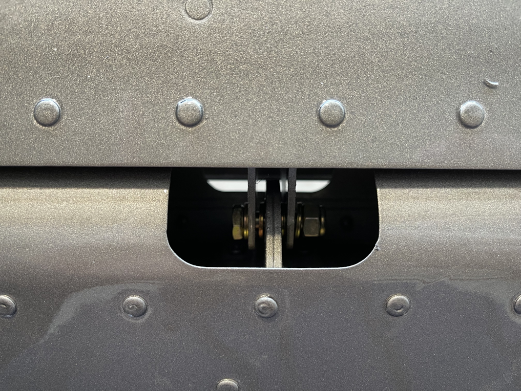
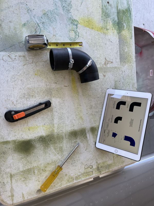
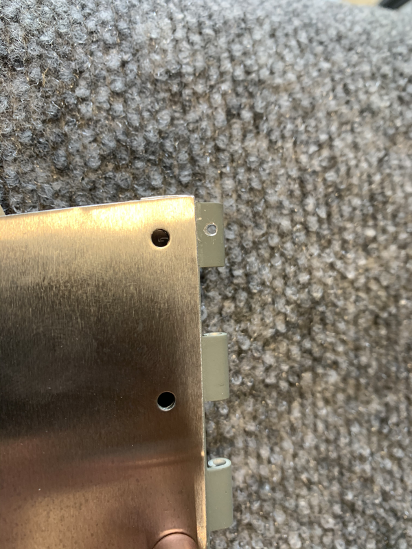
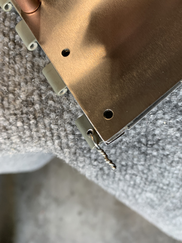
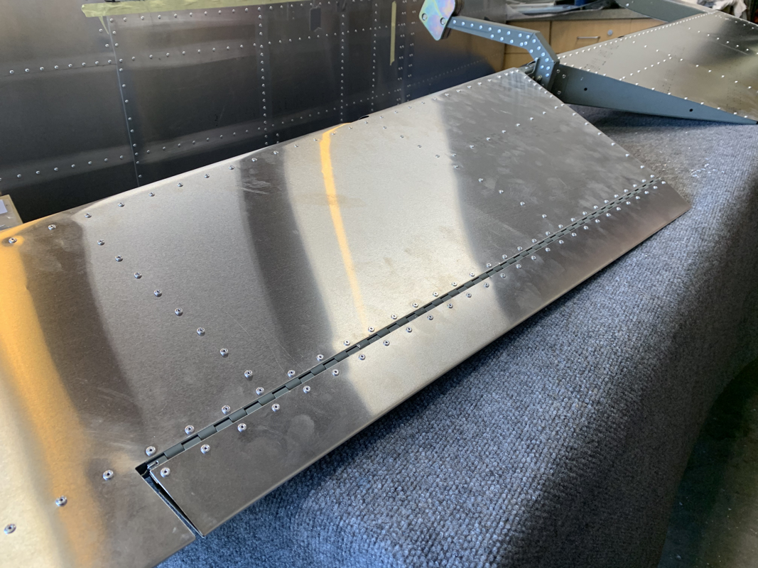
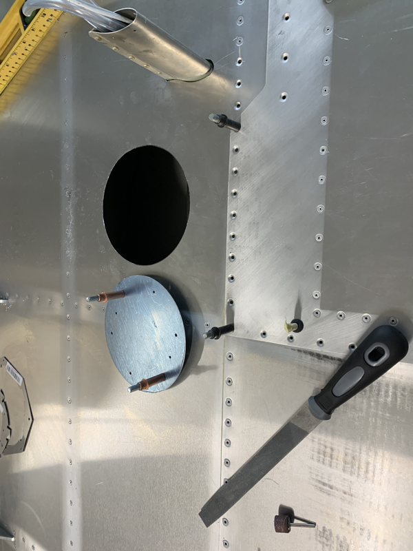
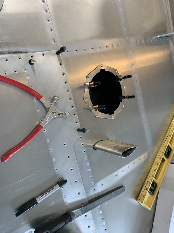
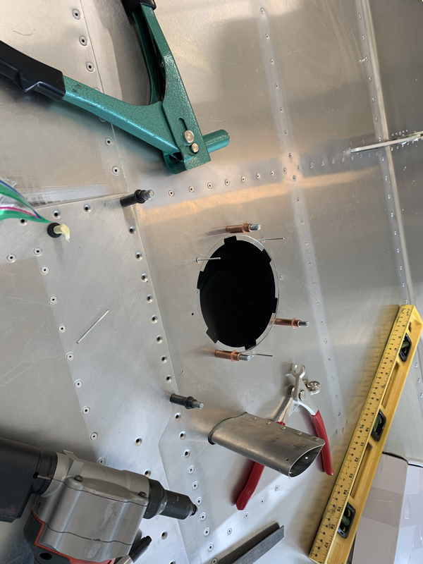
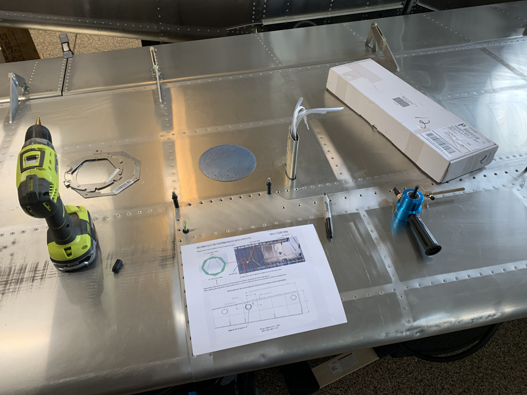
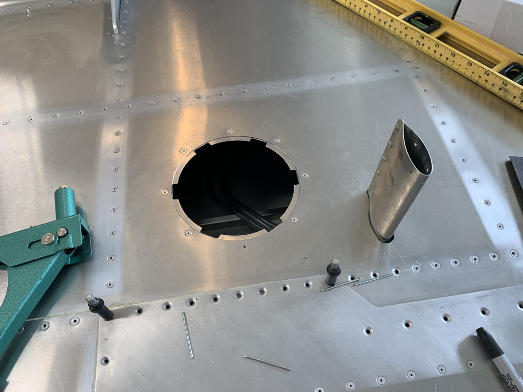
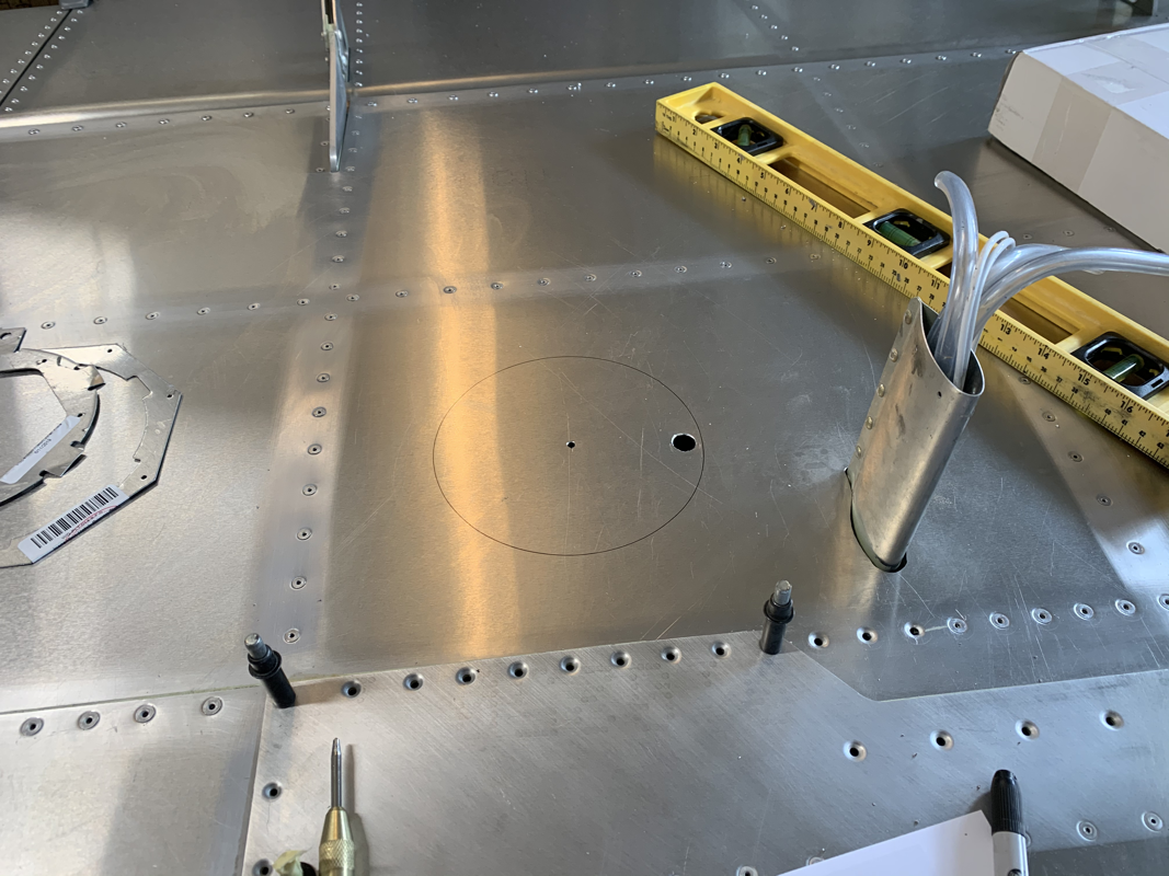
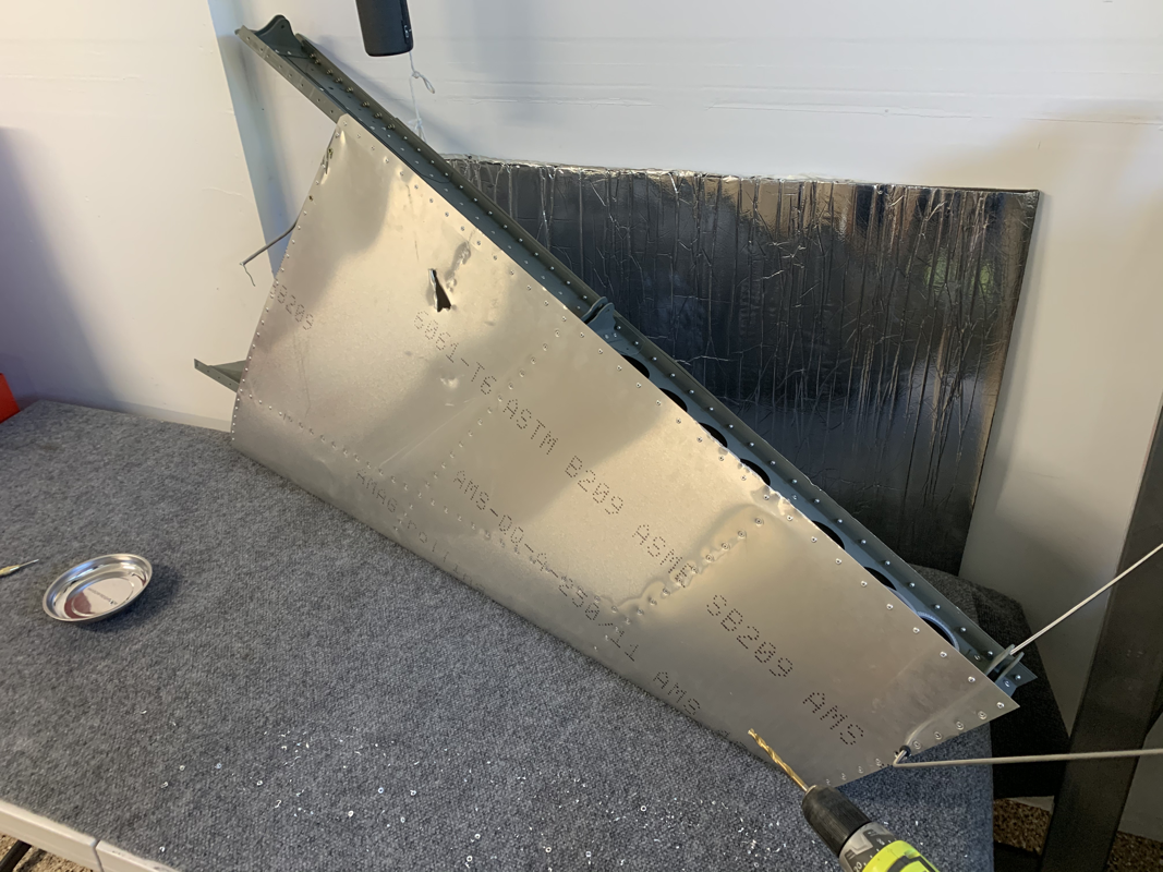
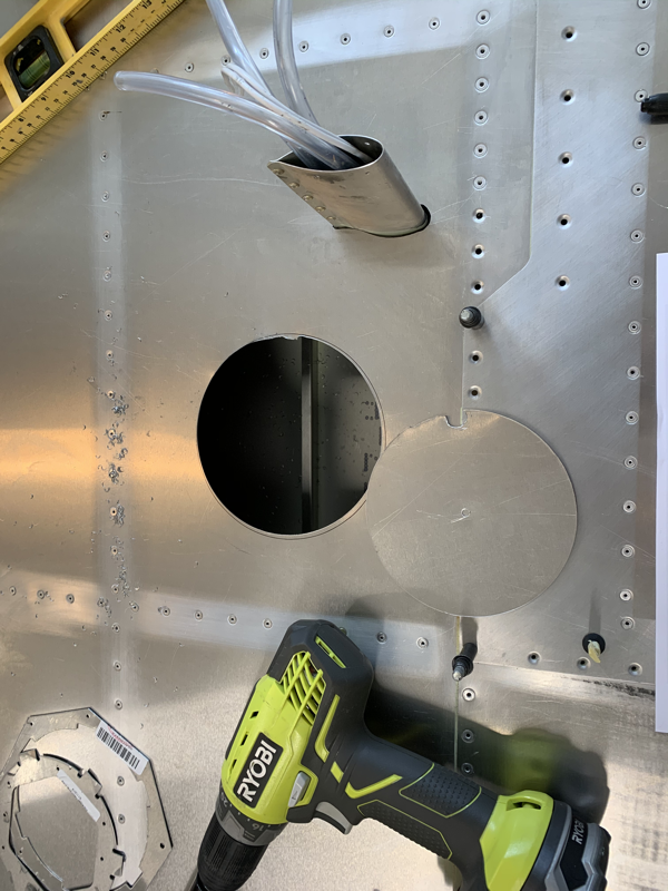
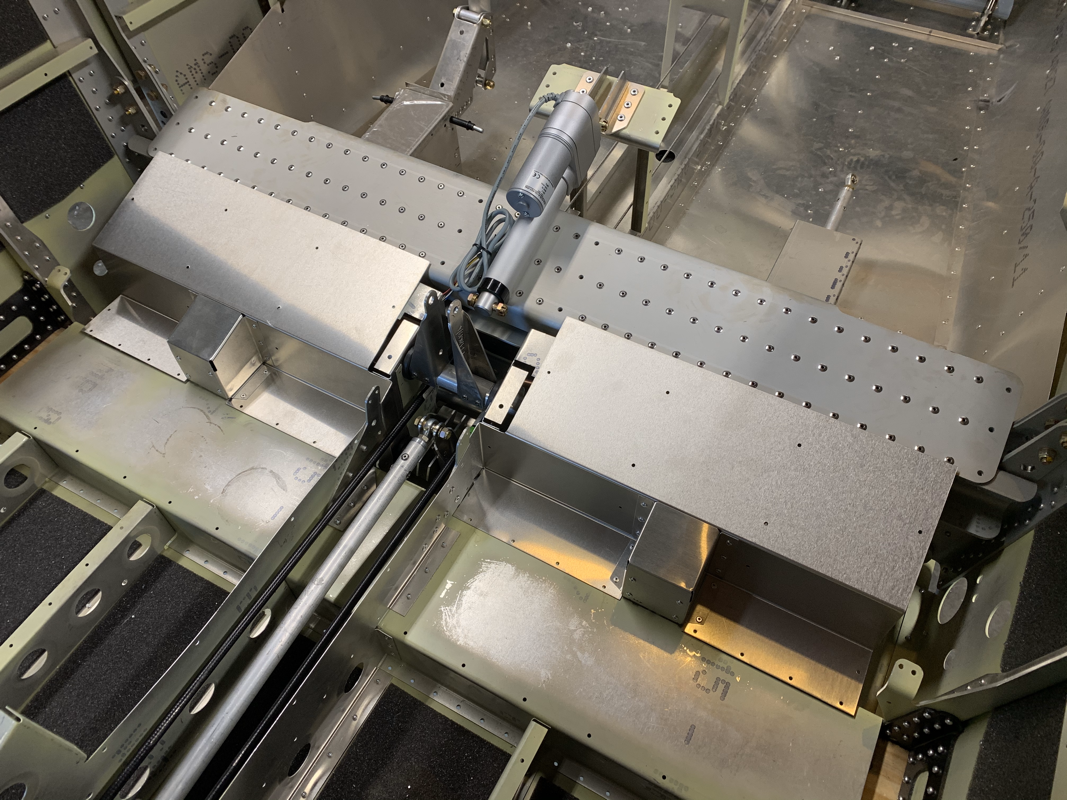
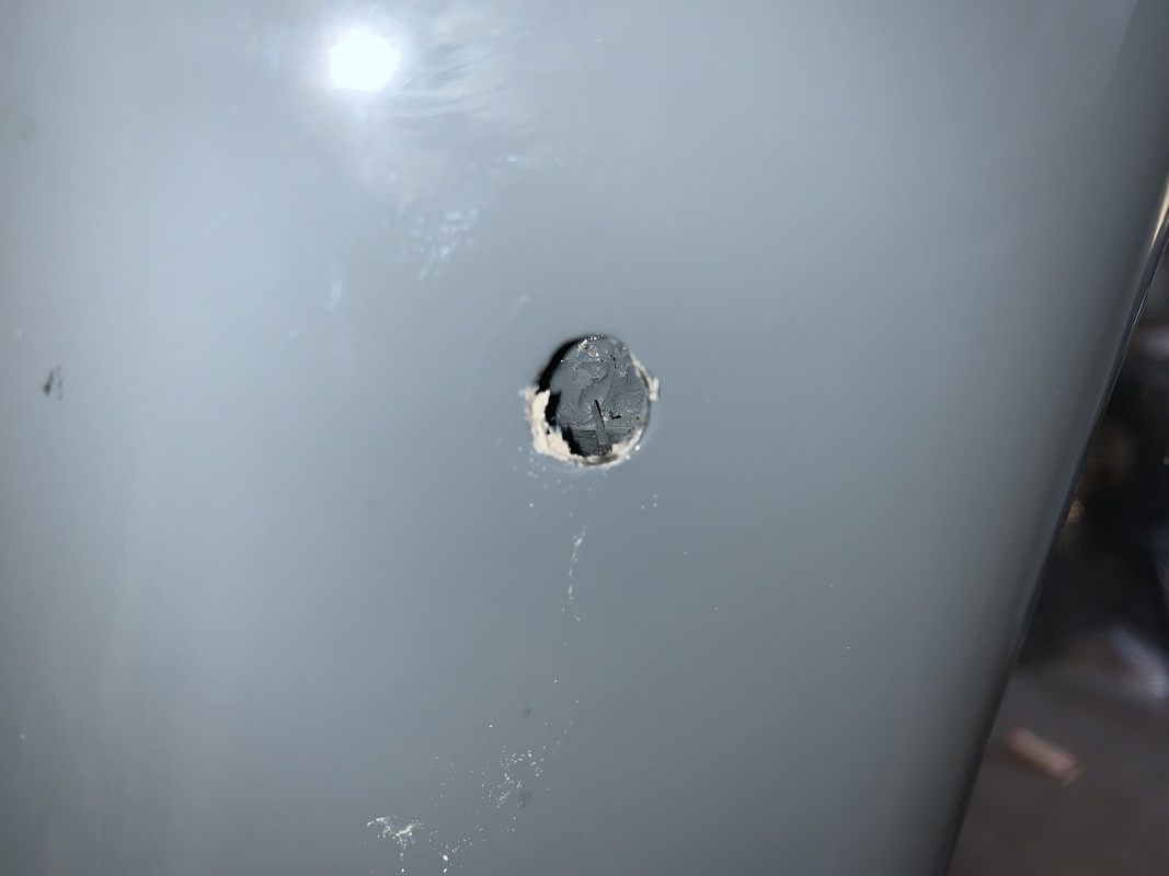
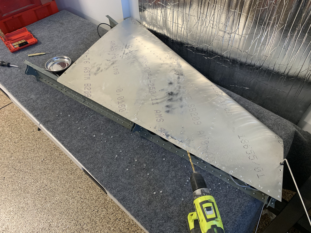
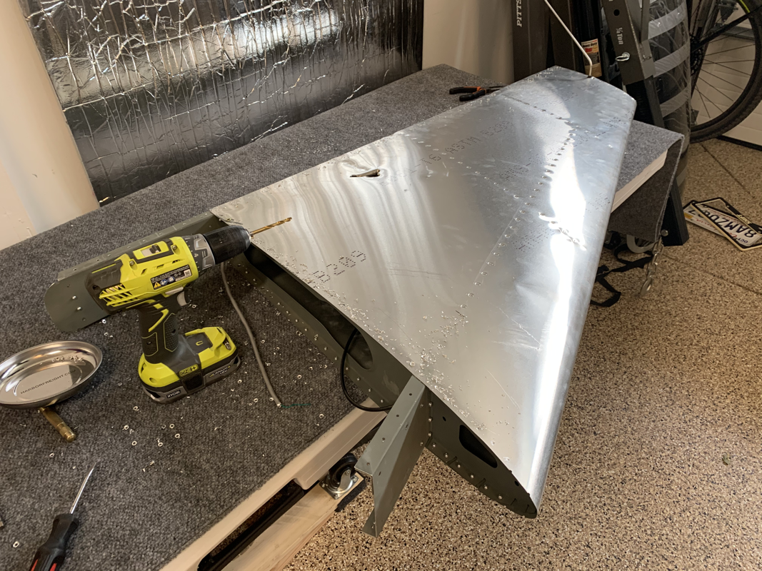
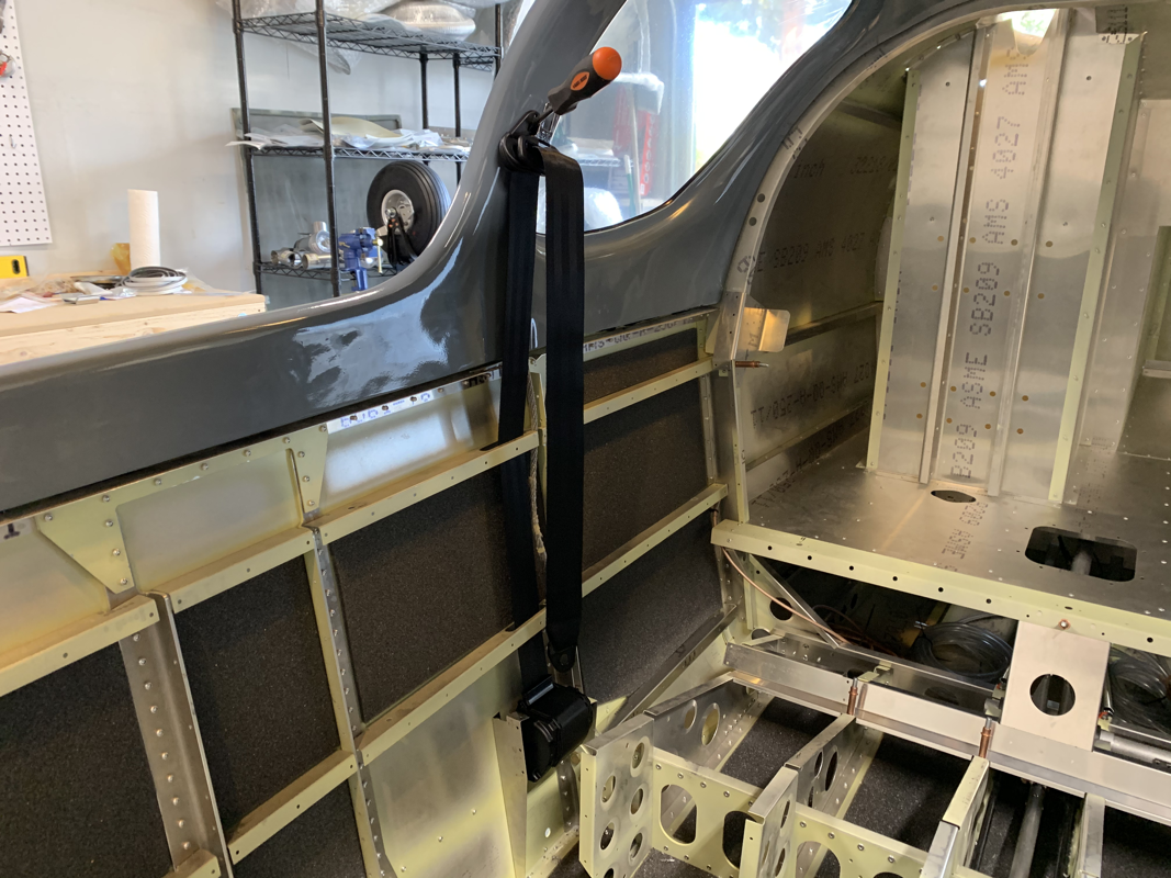
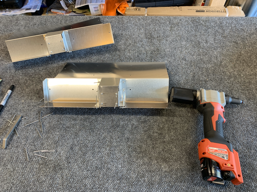
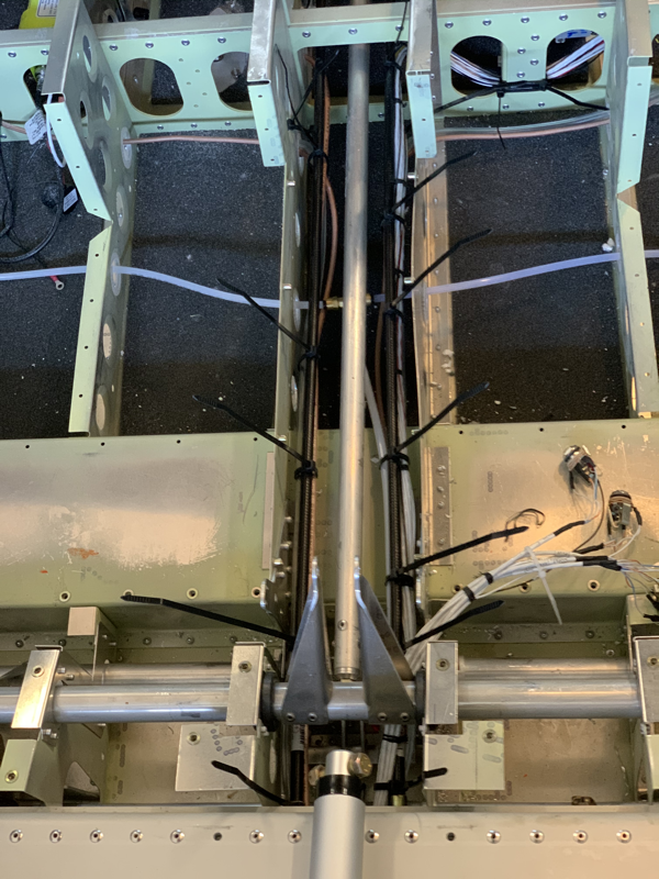
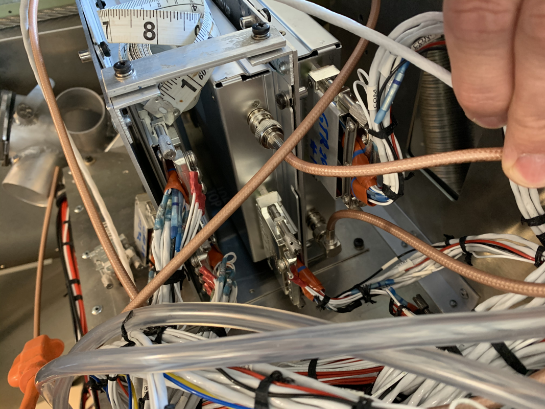
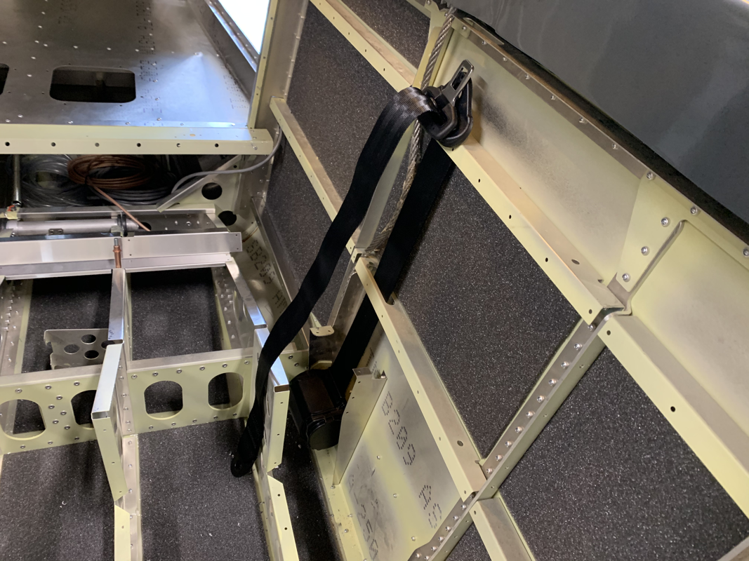
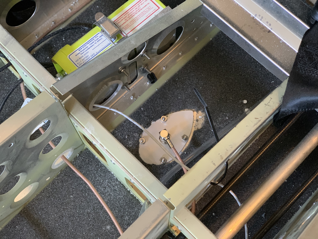
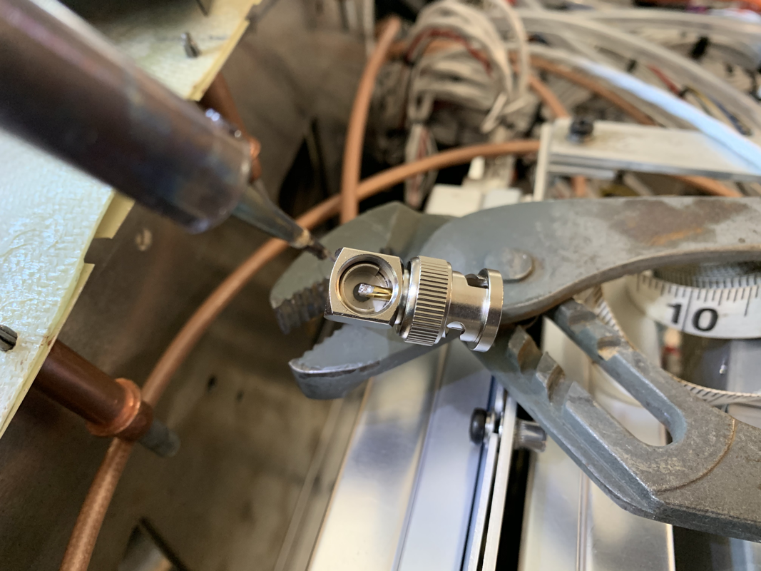
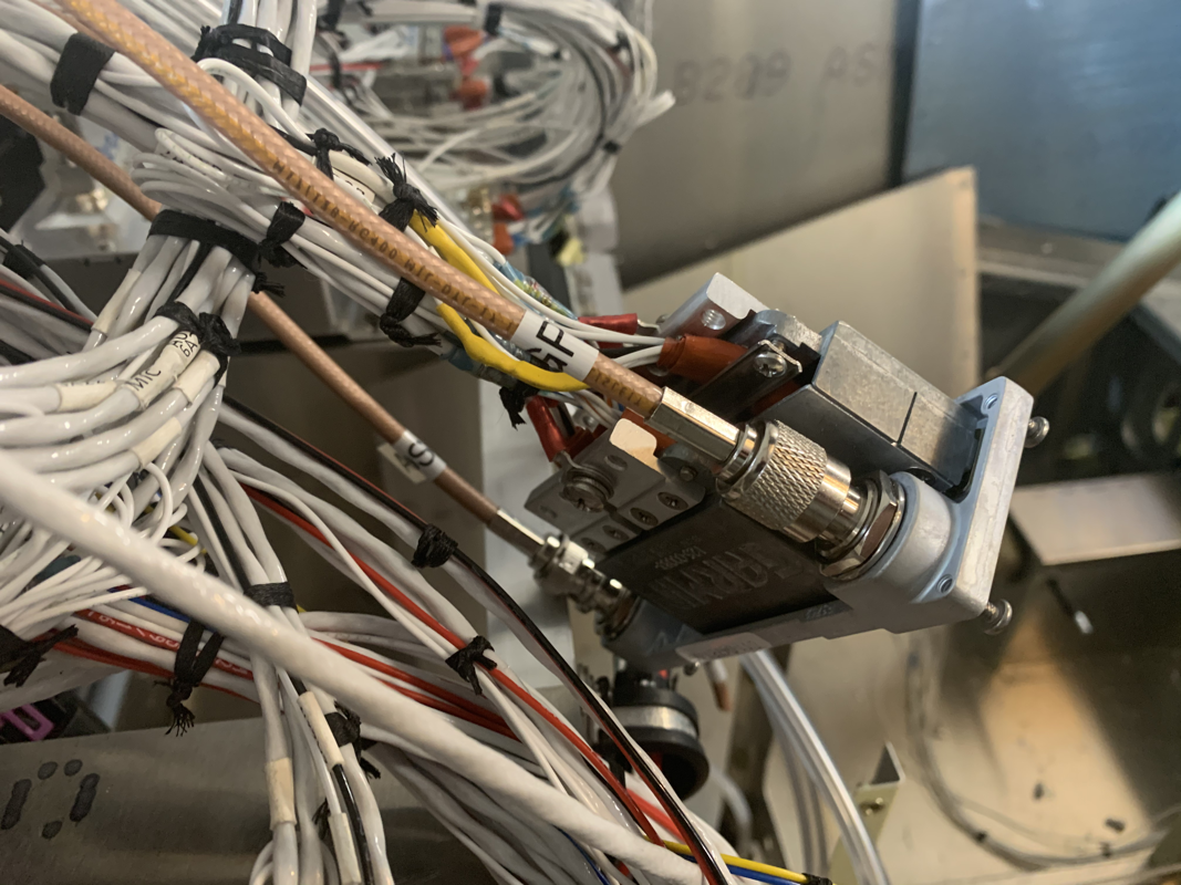
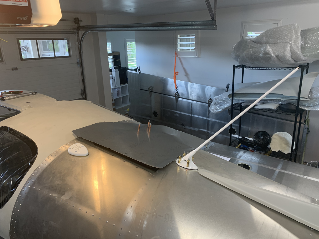
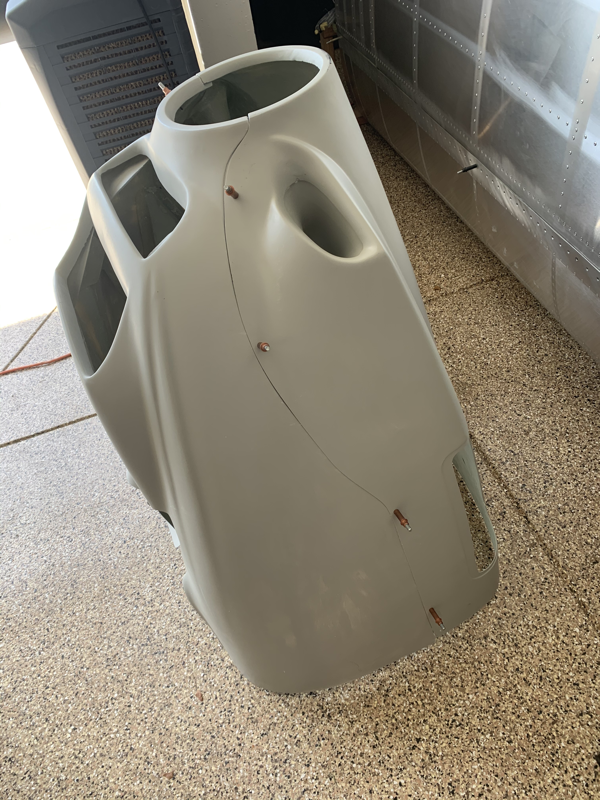
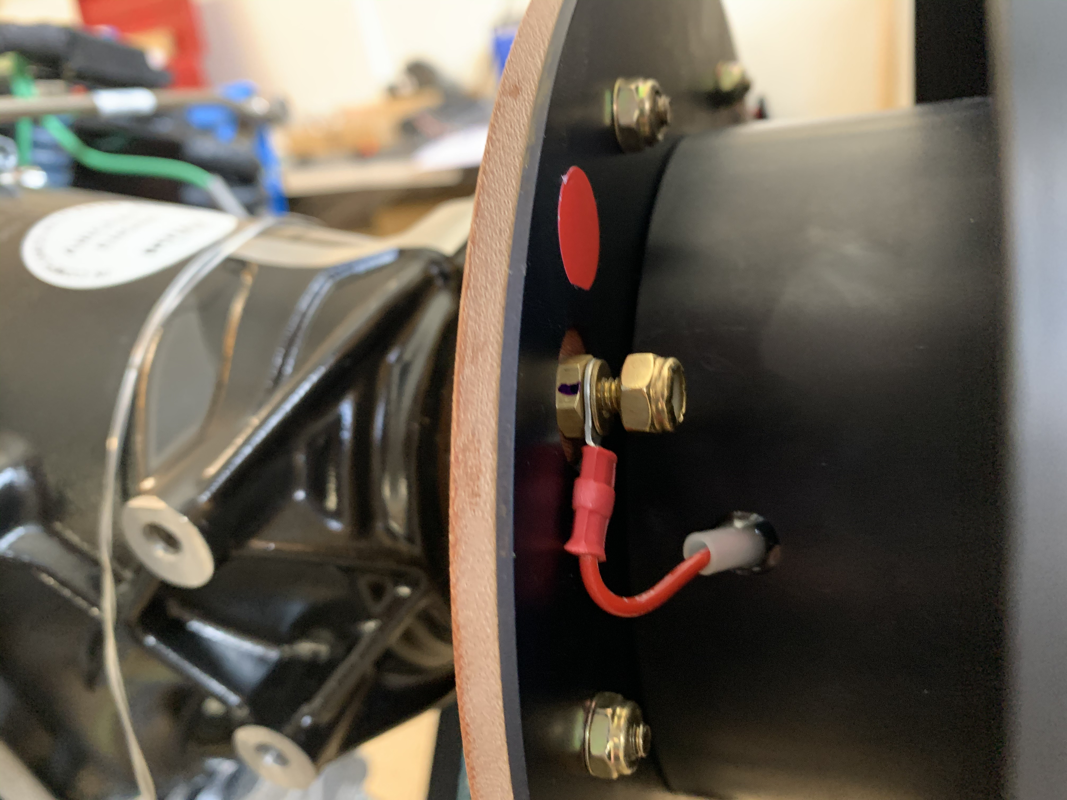
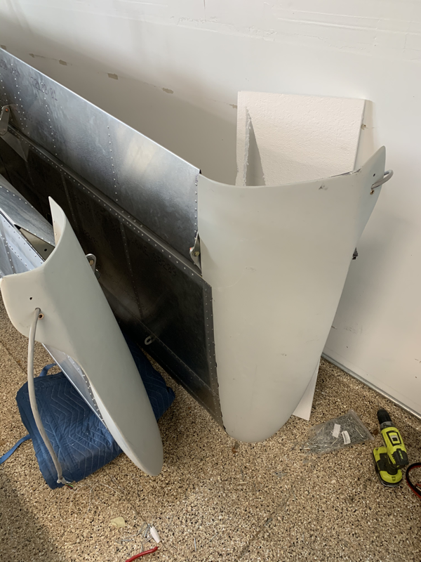
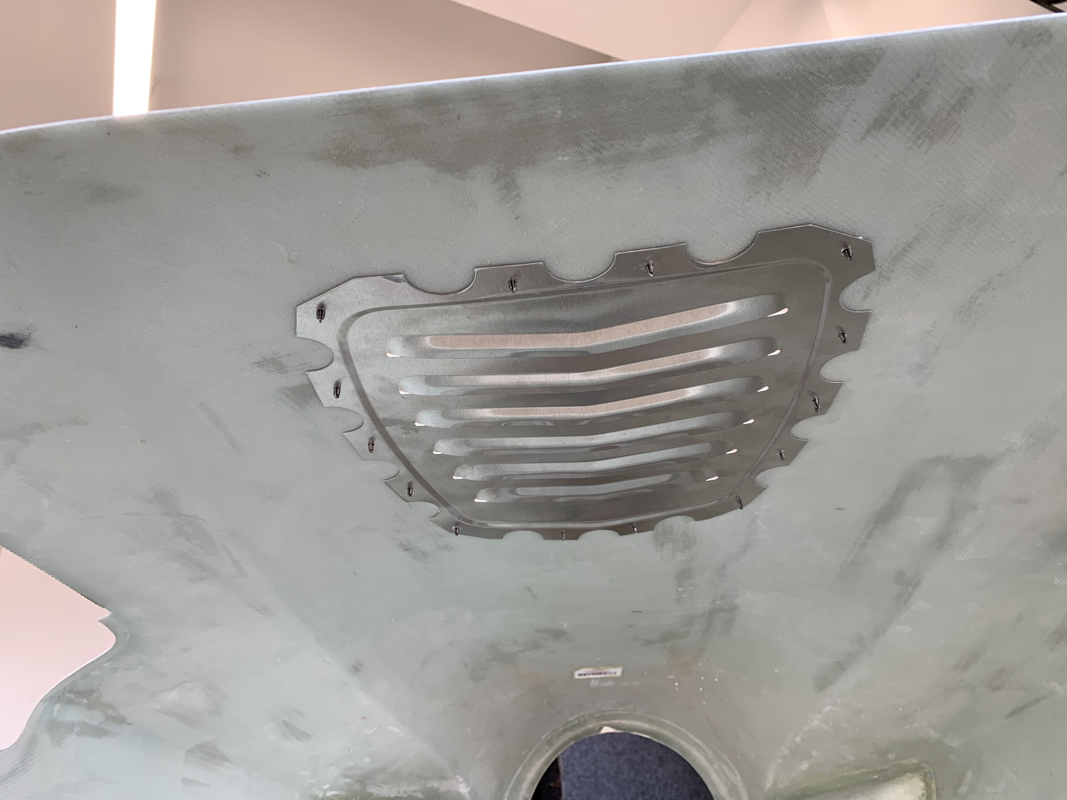
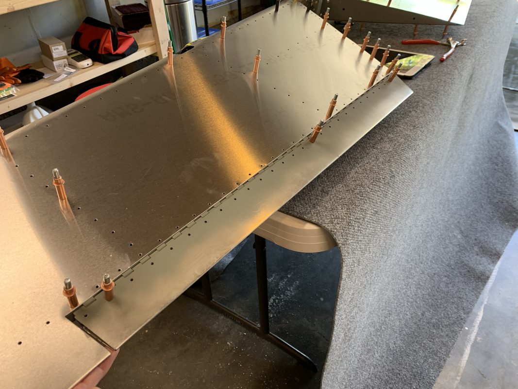
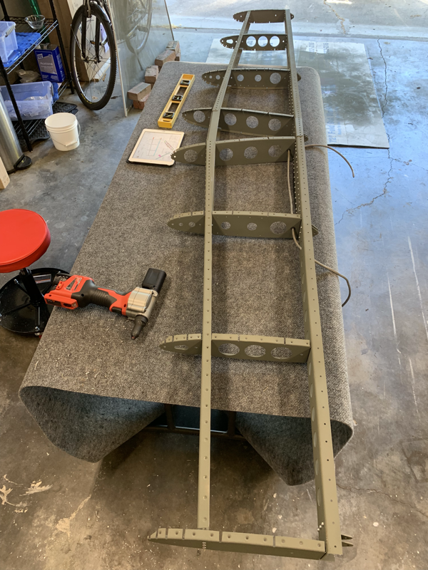
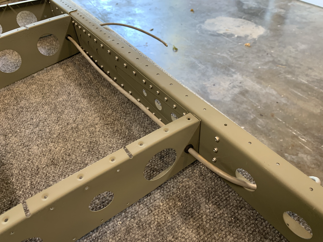
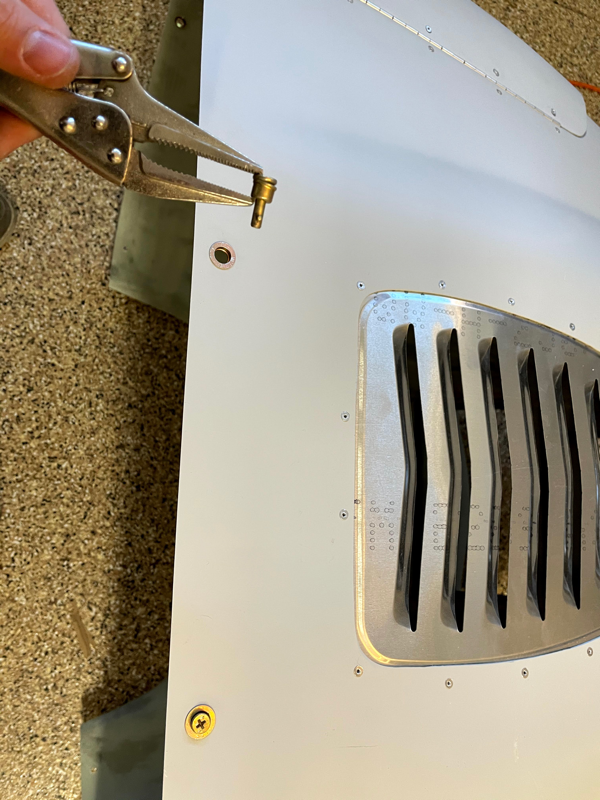
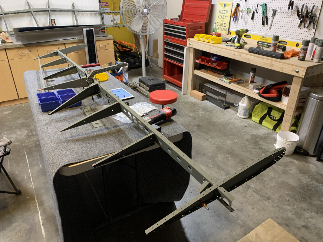
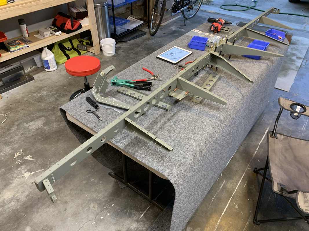
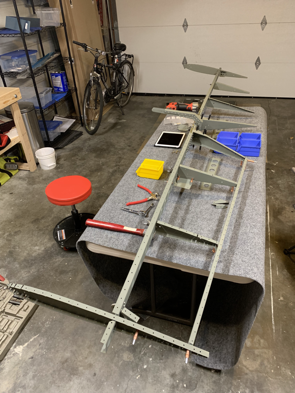
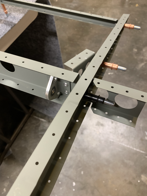
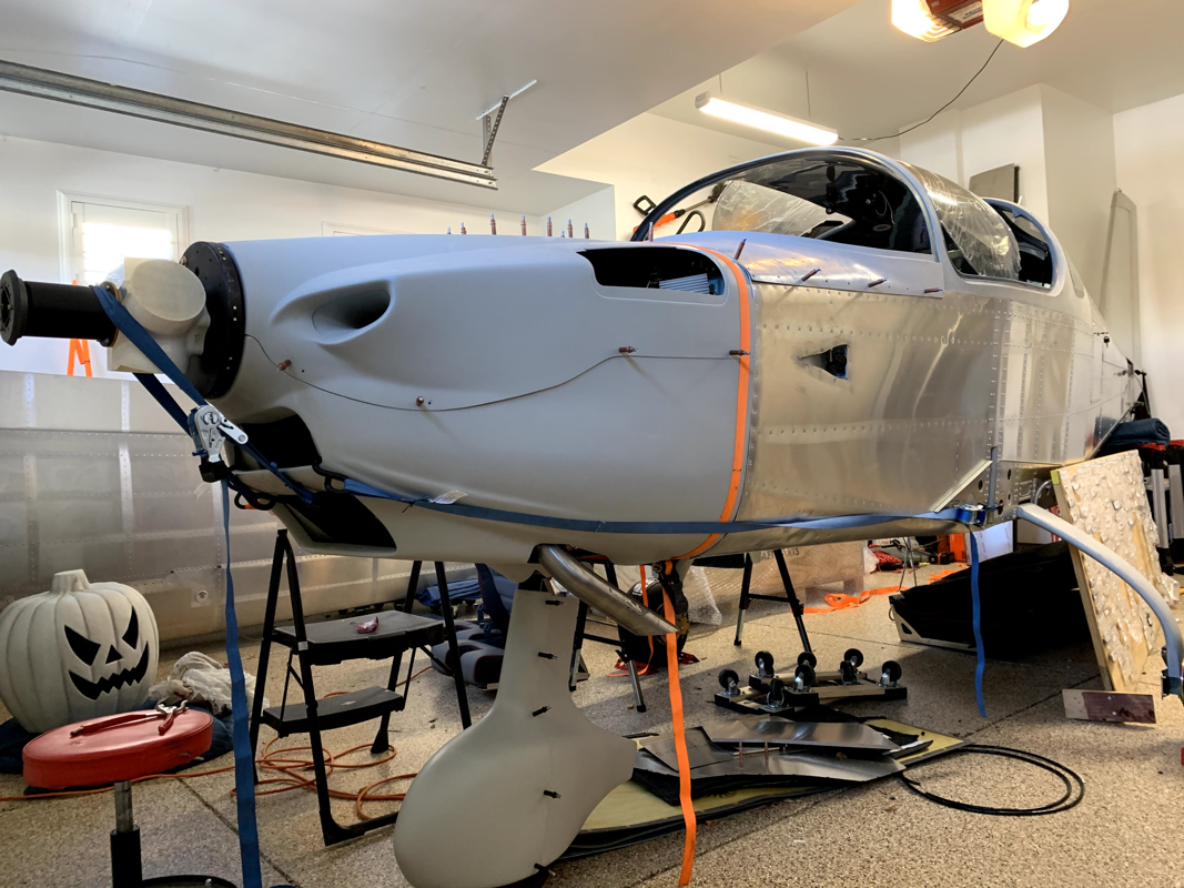
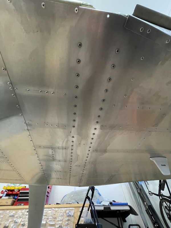
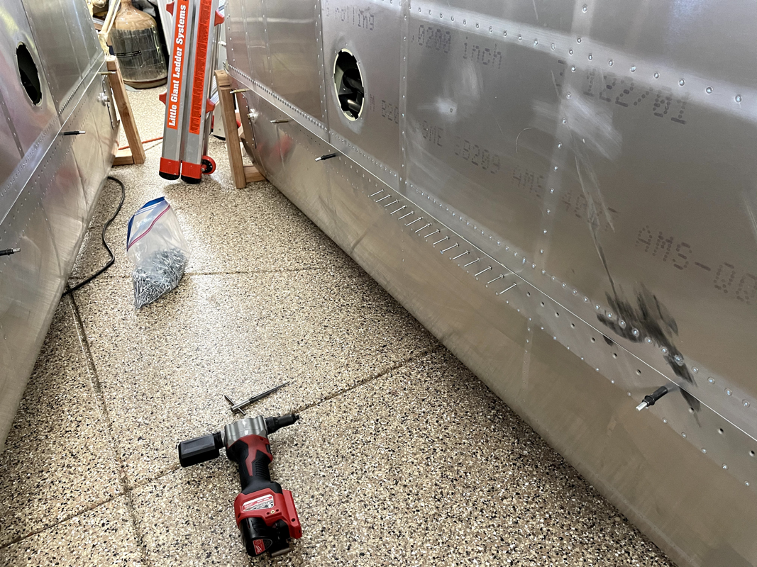
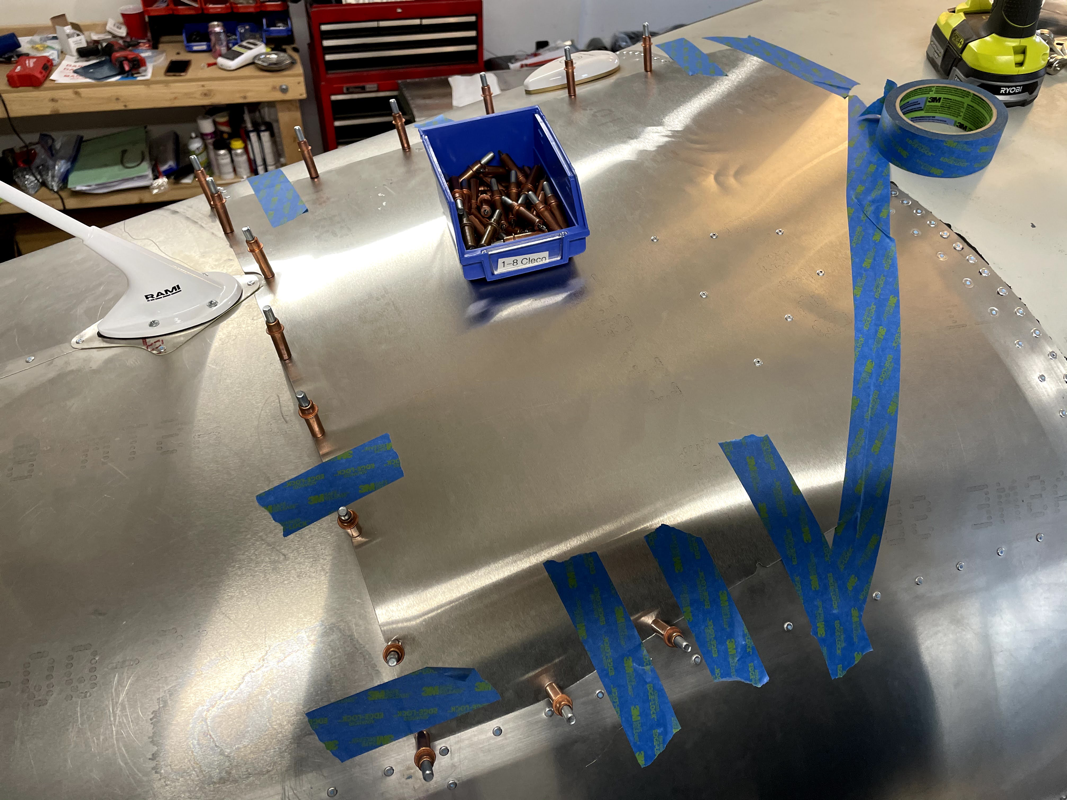
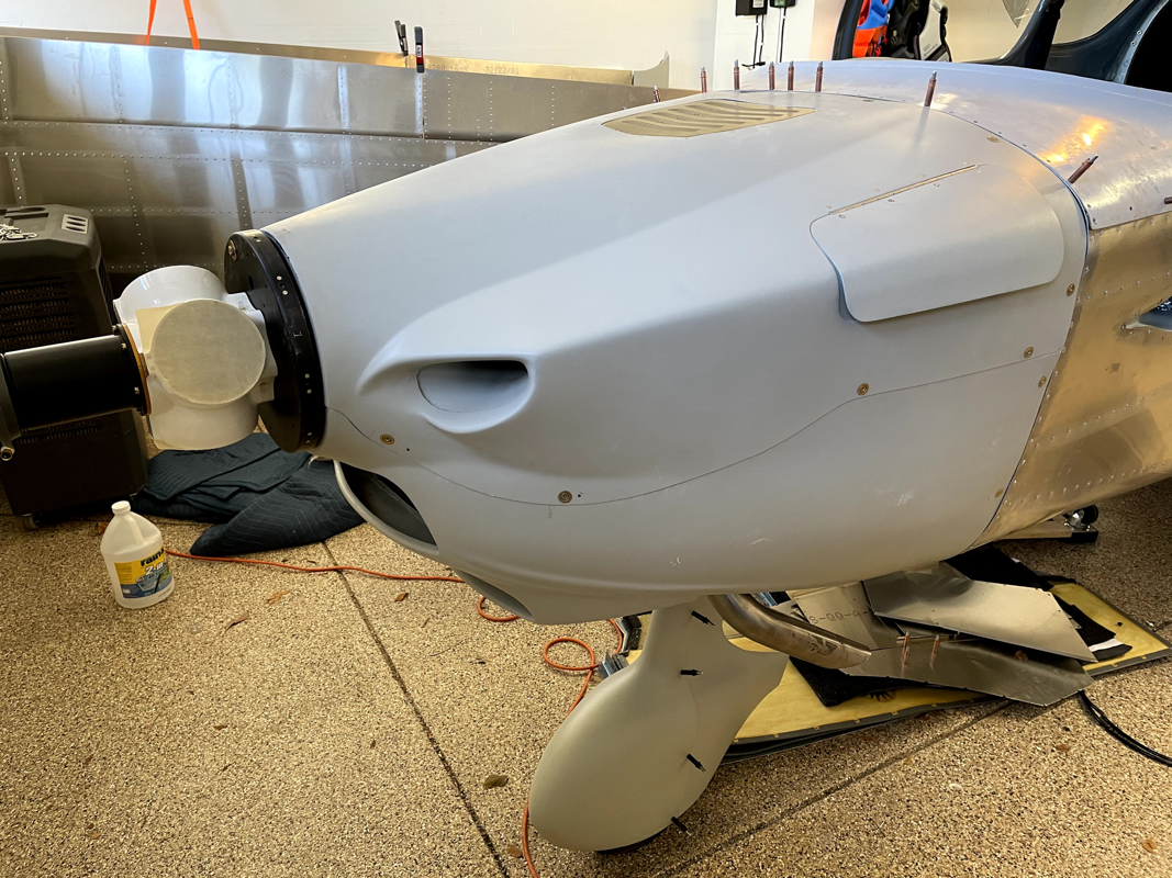
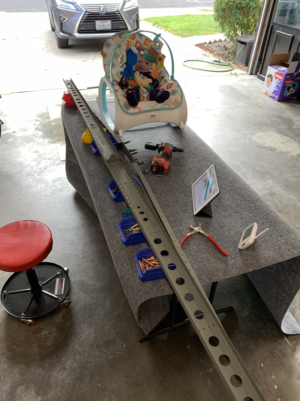
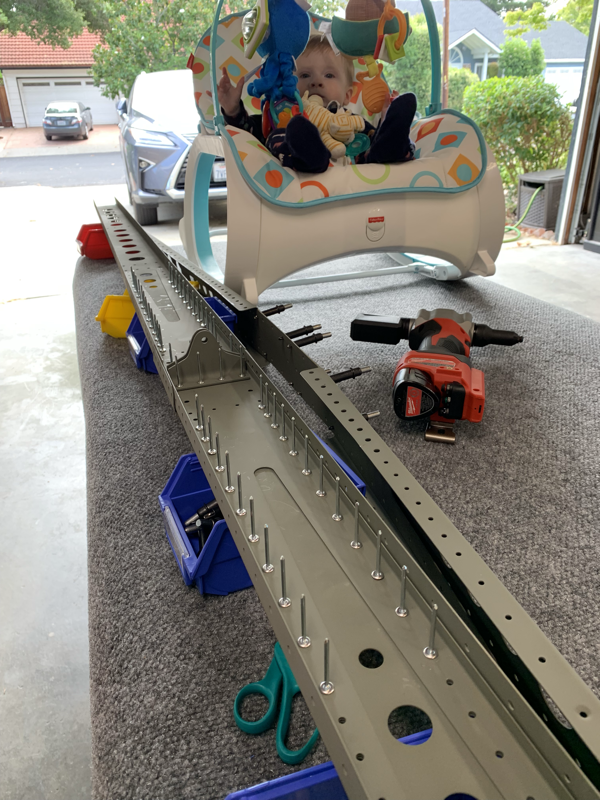
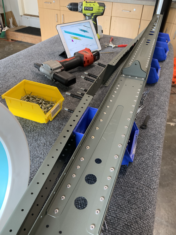
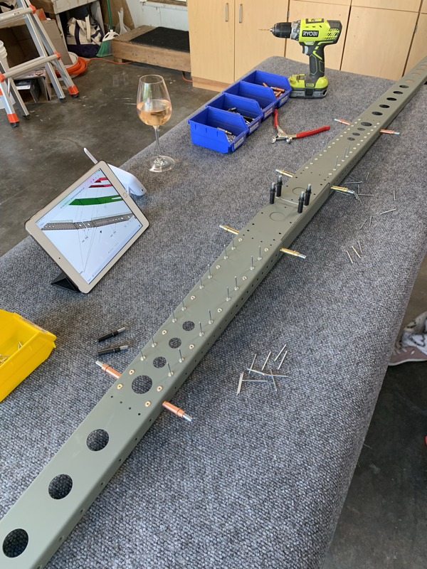
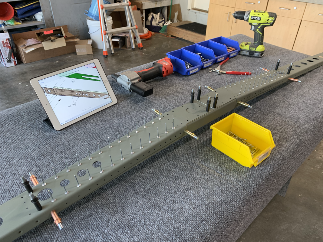
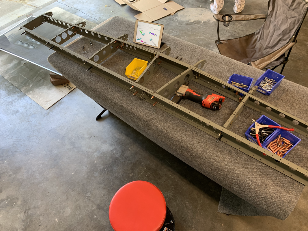
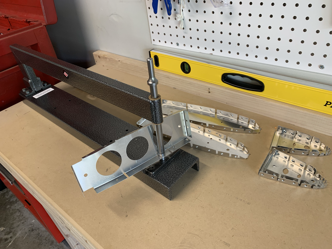
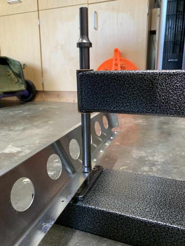
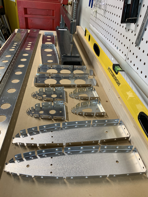
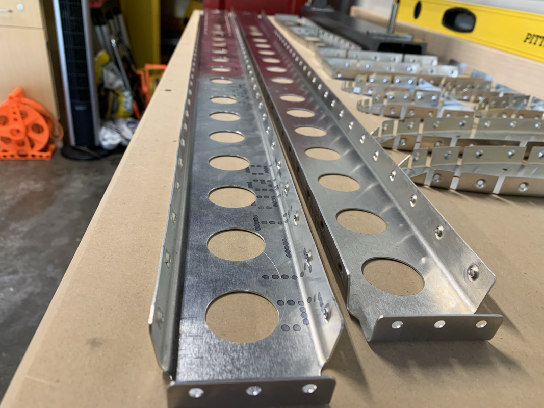
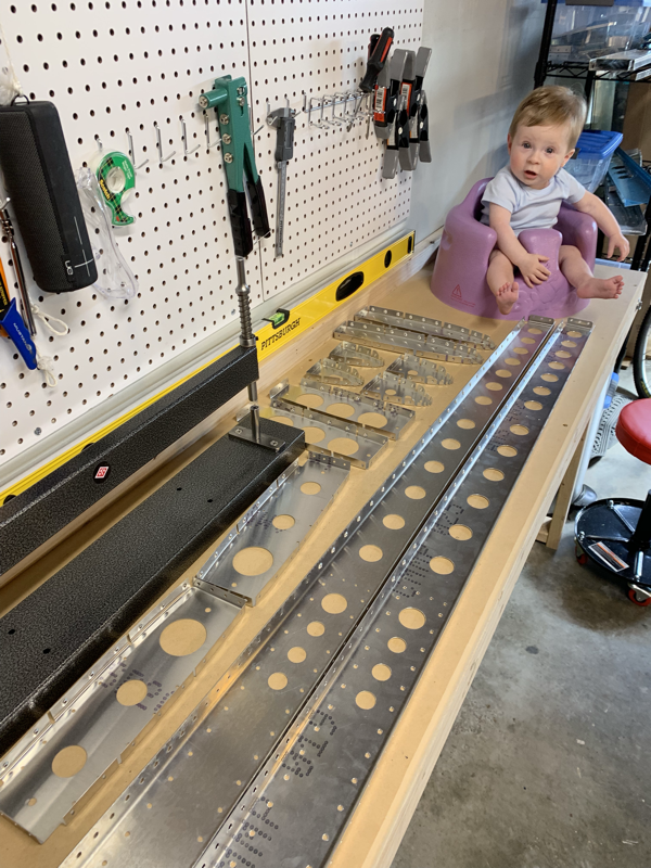
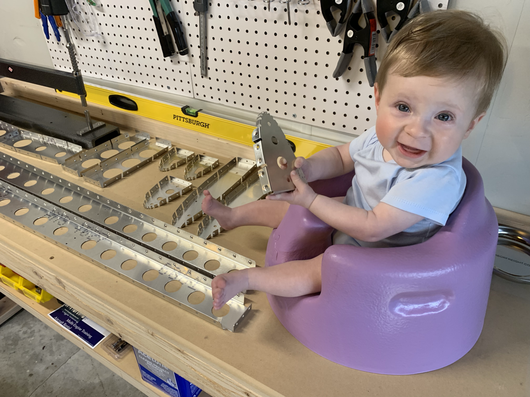
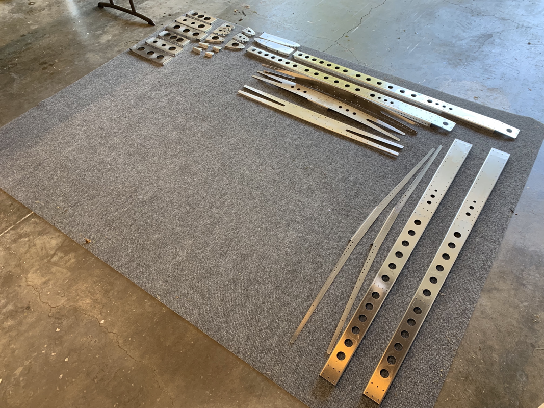
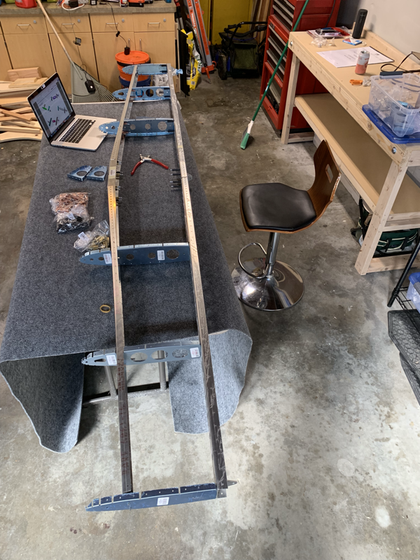
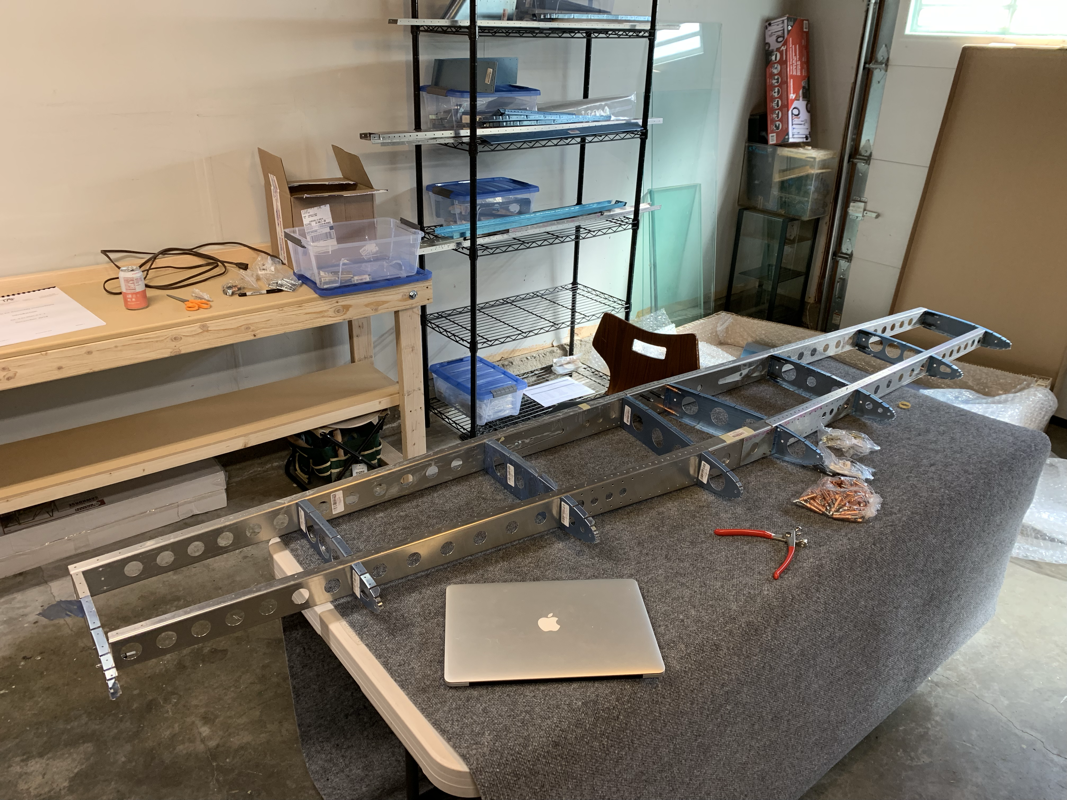
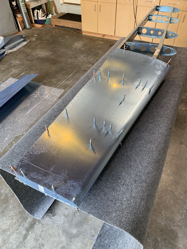
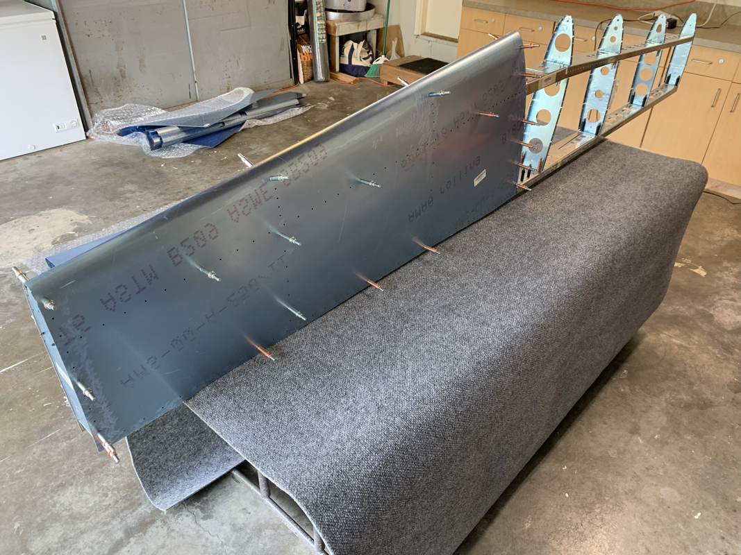
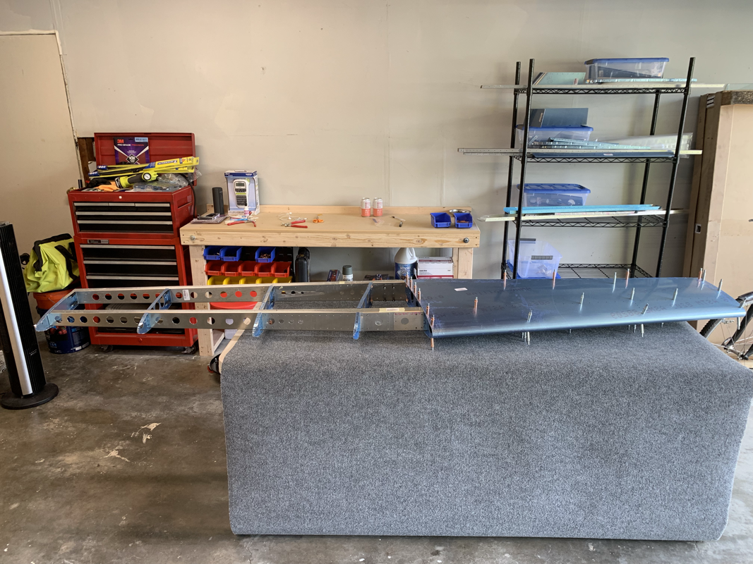
Thinking video updates are better to do than writing updates with pictures. Plus, seems it’s a bit easier to provide context. I recently received another trim tab as the last one was a bit twisted. I took this opportunity to add the safety wire to the piano hinge as other builders have done. The piano hinge is convenient to use, but the wire that is inside can vibrate out of the hinge so the recommendation is to secure both ends with safety wire. So I had to figure out how to best fit the VOR Antenna and run the wire through the ribs since the instructions only account for a Tail Position Light OR a VOR Antenna. This is to ensure there is no electromagnetic interference of the VOR Antenna. However, with the low power requirements of modern LED lights make this a bit less concerning, so I opted to do both. In order to accommodate the second wire running through, I drilled a hole on the top rib and put a rubber grommet through. From there, I could keep the wires separated on the front and back of the VS. From there, I was able to prime and apply the skin to the ribs, cleco in place and check the alignment. Straight as an arrow, so I began riveting one side. I checked alignment again and was still good, so proceeded to finish up. It was a bit tricky fitting the VOR Antenna. The antenna base is a bit tight against the rib, and it did cause a bit of a bump around the antenna on the skin. I don’t see that being a huge issue really. I did have to shorten 2 rivets to fit near the antenna. Glad to be done with the Empennage Kit! Now, I await the arrival of the QuickBuild Kit expected in mid to late October. Until then, my wife gets custody of the garage. ;-) I was able to spend some time finishing up the rudder. The main hurdles that took time were fitting the rudder tip and placing the VOR Antenna on the top rib of the Vertical Stabilizer. Placing the light was pretty straightforward, but when I went to fit the rudder tip, it was a bit too long. I asked Phillip how he went about it and he said to just trim the back a bit to get a snug fit. After that, it was just match drilling the holes and countersinking the first 7 holes. I saw a note in Phillips blog to pay careful attention to the number of countersink holes since the instructions say do the first 9, but there are only 7 done on the skins. Once things all lined up, I went ahead and soldered the light wires and wrapped them with heat shrink. I added some wire protection to the part of the cable that is exposed outside of the skins. I did need to use the angled pop rivet tool on the bottom of the rudder, as it was pretty close quarters to the plate. I did a final check of the alignment and it was still straight. Feeling good to be almost done with the Empennage! Now to skin the Vertical Stabilizer to finish things up! I received the new set of rivets from Perry at The Airplane Factory in Torrance, CA and was able to continue putting the ribs together. I also worked on trimming the flange to better fit the bottom rib of the rudder. No more interference! I'm starting to skin both parts and check if there are any alignment issues, so far so good! Now I'm going to break out the soldering iron and connect the wires to the Anti-Collision/Beacon light on the rudder. I went with the Aveo Engineering Minimax Ariel. Since this is a permanent connection, I'll be using heat shrink sleeves to protect the connections. I will also be installing the VOR antenna in the Vertical Stabilizer. I see the manual recommends that you don't install both due to possible interference, but with the low voltage of modern LED's I don't see that being an issue. I also see that Phillip went the same route with his Sling TSi build. This time I did the cleaning, scuffing, degreasing and priming of the Vertical Stabilizer and Ruder in a batch. This seemed to speed things up since I already had everything prepared and lined up to use. I just had to make sure the parts were different enough that I could tell what goes where when it comes time to assemble it all! I did notice that the flange at the bottom of the rudder (Last Photo) does rub against the rib. It causes it to expand, leaving the skin to be uneven and would probably be an issue. Mike Black from Sling Central had also mentioned this issue and came up with a slight modification that seemed to work well and doesn't affect the structural integrity, so I'll be making the same fix. Overall, these parts are coming together a lot more quickly than the Horizontal Stabilizer and Elevator. Progress! Until, I ran out of 4mm x 10mm rivets. I'm also looking to be a bit short on the 3.2mm x 8mm rivets.. Perry from The Airplane Factory in Torrance, CA is sending some over and will pick things up from there. I spent some time countersinking the end caps and dimpling the skins. I read some other builders had some concerns over the material being too thin, but it seems they beefed up the thickness to allow for a good countersink. Once that was done, I temporarily connected the elevator to the horizontal stabilizer with some bolts I had laying around and used some wood placed on the skins secured with some clamps. This ensures the elevator and horizontal stabilizer are perfectly aligned. I made sure to only cleco one side at a time, per the instructions, and began riveting. The skin fit pretty well and didn't really have to ream out many holes. I flipped it over and repeated the process. The skin was a bit tighter on this side and took a few more clecos to ensure a good fit. Nothing more satisfying than a handful of pulled rivet mandrels to finish off another piece! I was able to finish up the Horizontal Stabilizer ribs and dimple the rest of the skins. I pulled the wire through and now I just have to apply the skins and make sure everything fits again. It's feeling like déjà vu, cleaning, degreasing and priming the elevator parts.. one of my least favorite activities of the build process, but necessary. At least now I'm getting a streamlined process down. I primed the elevator parts and let them dry for a day. Came back to it and started riveting! This assembly is definitely a bit more complex and took a bit more time to study the instructions. On the swing arm assembly, there's a hard to reach rivet right next to the bracket. You'll see that one missing in the photo. I figured I just get some small M2.5 hex bolts and stack them about a quarter inch until it is flush with the nose of the rivet gun, then give it a pull. Worked like a charm! I did find some discrepancies in the instructions with rivet sizes, seems the descriptions of the rivet sizes are different and different parts provided in the kit than referenced in the instructions. The description in the instruction says it is a 3.2x13.6mm Alu Domed Rivet, but the actual rivet size received with the part number in the kit is 3.2x12mm. Additionally, the instructions say to use 4.8 x 12mm rivets HW-RIV-164-X-X-0, but the kit for elevator parts only includes 4.8 x 15mm rivets HW-RIV-165-X-X-0. I made sure that there weren't any other locations needing 4.8mm rivets and went ahead and used those. And of course, while feeling like I was on a role, fate seemed to occur. While torquing the bolt on the swing arm assembly, the bolt actually snapped off. Now I have to source another AN3-13A bolt and take another look at the torque required. It's ok, I'm sure it's not going to be the last 'oops' moment and I just look at the new shop sign from EAA - "Keep Calm and Build the Plane." ;-) I also ran into an issue with the bracket that connects the swing arm to the ribs not being aligned. I checked with TAF and they said to just drill up a size and use a 4.8mm rivet. Seemed to do the trick. On another note, I did add a tab with a chart for my hours by category. It finally felt like I made some good progress today! After spending hours dimpling, cleaning, degreasing, and priming.. it finally came to the point where the parts were ready to put permanently in place. It was a bit nerve wracking the pulling the first rivet, I must have checked the plans at least 5-6 times to make sure I knew exactly what to expect. Of course, after a dozen or so rivets, things got into a good rhythm and I started to trust myself. The Milwaukee Rivet Gun makes this process really easy, great suggestion from other builders! I was quite happy that there were only 5 or so holes on the rear channel that needed to be enlarged with a chucking reamer.. just off by a hair. Enough the rivet couldn’t easily drop in. It also helped that I had my project manager and quality control person keeping me on track. Thanks Son! Our flying adventures are still on track thanks to your motivation. ;-) I did find out that I forgot to order the right sizes countersink bit. As soon as that comes this week, I can finish up the ribs and work on applying the Horizontal Stabilizer skins. While the rack of ribs were on the grill for the 4th of July, I had some free time to get some more work done. I'm following the method that others have done. (Other blog links on Resources tab)
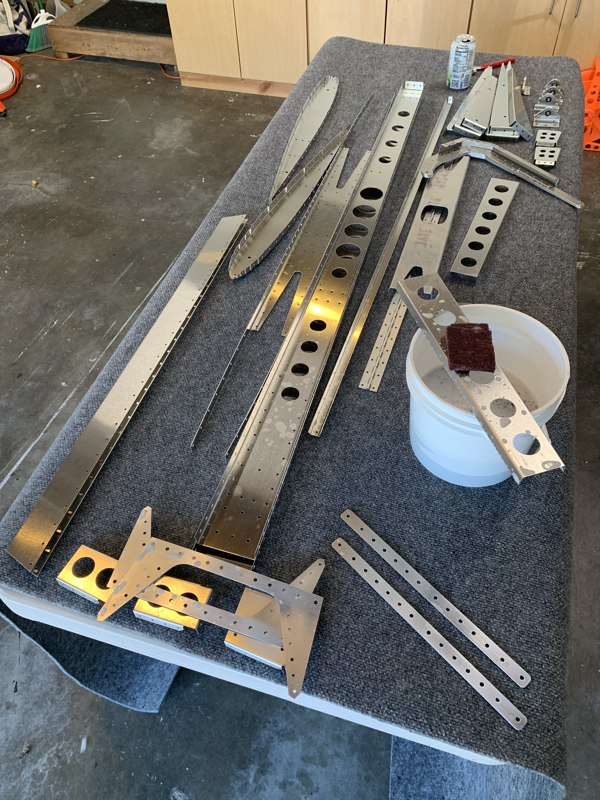
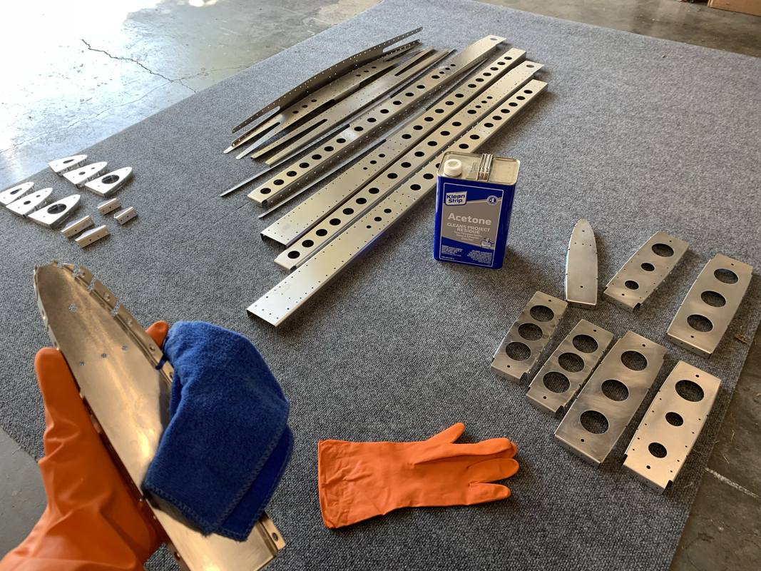
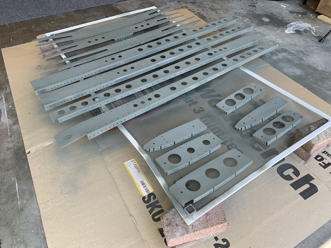
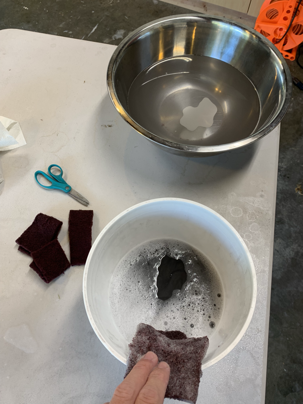
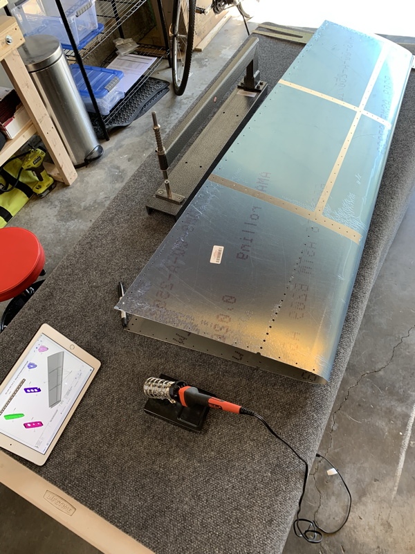
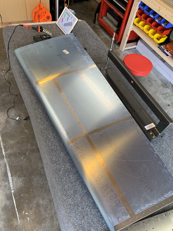
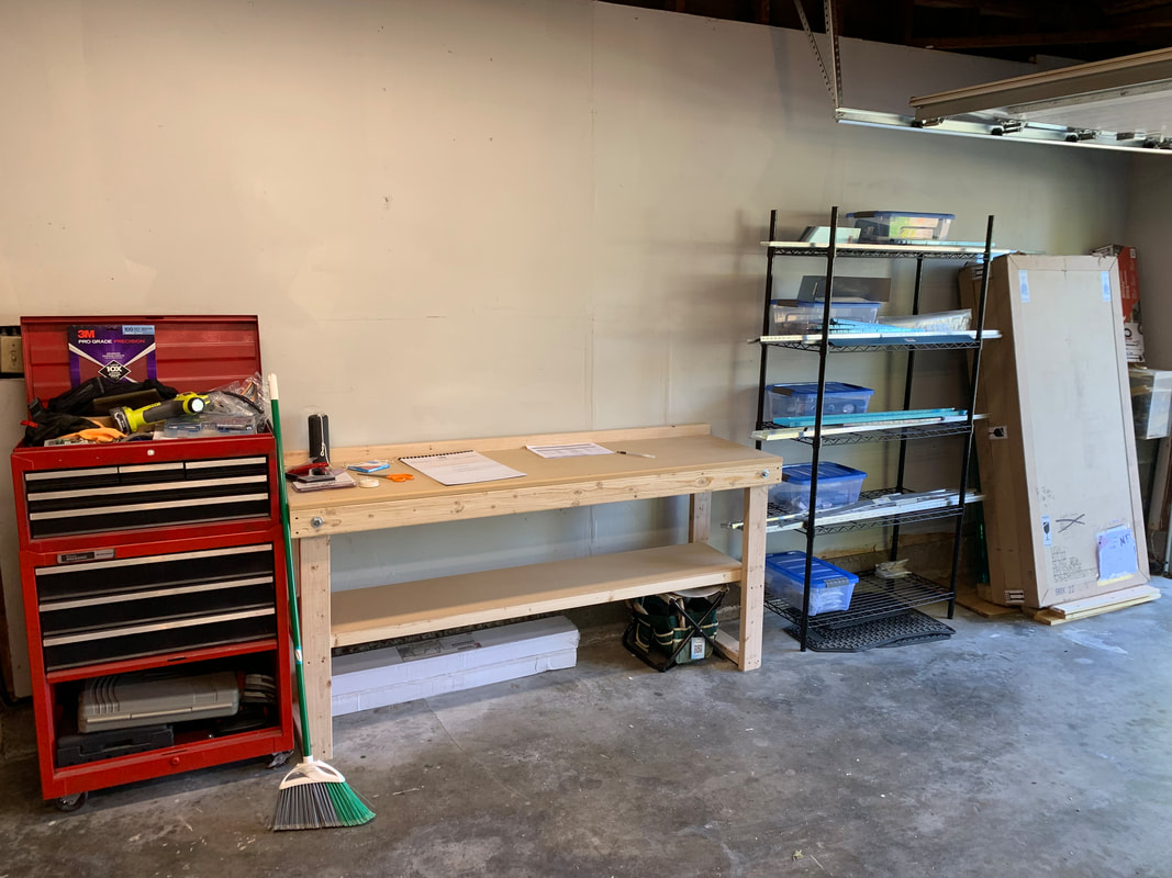
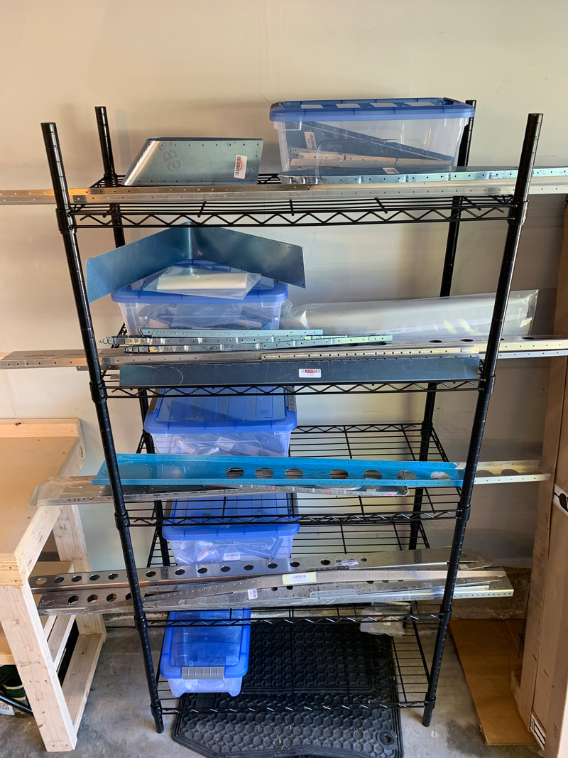
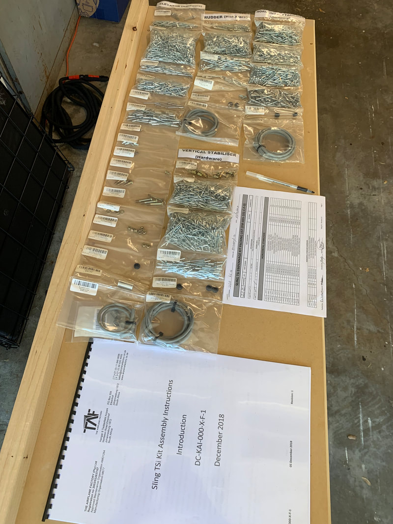
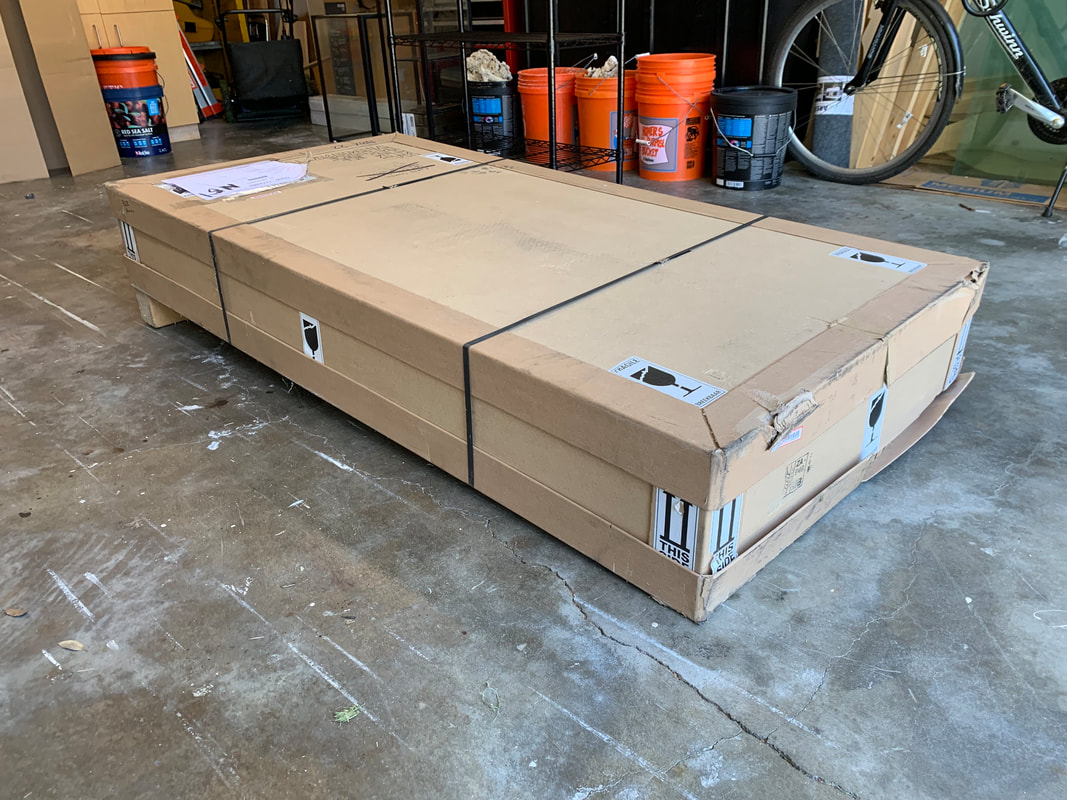
I was able to get as far as getting a single primer coat on before I had to do some more food prep and, well, my can of primer ran out. Definitely need to grab a few more tomorrow and looking to finish up the Horizontal Stabilizer this weekend. Also, I put an order in for the RAMI AV-12 VOR antenna, so that with the position light I already purchased, I should be good to go for the empennage electronics perspective. Now that I have the C-Frame, I started dimpling the horizontal stabilizer. Overall, it was a pretty quick exercise to dimple the ribs and spar, only a half hour. However, the spar is pretty thick, so it took a few extra wacks! I wasn’t sure about the quality, so I had my helper check my work and he gave me the thumbs up! Next up is dimpling the HS skin. Will get to that tomorrow! Well that was a task.. using some Simple Green 1:1 mix with water with a red Scotch-Brite scuffing pad took quite a while! I focused mainly on the areas that would be a ‘mating’ surface and that still took close to 1.5 hrs. The water sure did get dirty as you’ll see.. the aluminum ‘looked’ clean but I’m sure it goes through plenty of machining before it gets to the final product. As I saw on another blog, I removed the blue coating on the skins by using a heat iron. Simply run it across the coating and it will peel off! Now no need to worry about extra scratches on the skin until I’m ready to finish. Next up is making absolutely sure there’s no grease on the parts by using Acetone prior to priming. Maybe I can get the wife to help me next time for an extra set of hands? 🤔 I spent some time this weekend thoroughly reading through the manual and decided to give the horizontal stabilizer a shot. I wanted to make sure all the parts fit and see where I might need to do any match drilling. To my surprise, it came together rather quickly! For someone who hasn't done this before, reading the instructions the first time, I put together the HS in about 2 hours from start to finish. Putting on the skins, I identified only a few areas where it might get tricky, but I don't think I'll need to do any match drilling. Most of the holes lined up perfectly! Now that I have a good idea of what needs to be done, I'll be disassembling and getting the parts ready for dimpling and priming. I ordered a C-frame dimpler and should arrive next week. I also set up an appointment with a local EAA Technical Counselor to get acquainted and start the process. I'm so excited to finally receive my first shipment! It's starting to feel real - it's been 3 months since I put down the deposit for the kit. Now the fun begins... I spent the first hour or so reorganizing the garage to create a workspace. Then finally cracked open the box and started the process of inventory. Checked off all those boxes! Now things are neatly organized by tail section, I am shopping for the ILS/VOR antenna and the tail position light. I went ahead and purchased the Aveo PosiStrobe MiniMax™ DayLite Red. Still looking into the antenna options. Now to educate myself on all the different priming options! |
Archives
September 2021
Categories
All
|


 RSS Feed
