|
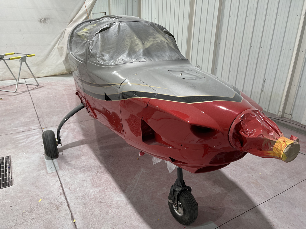
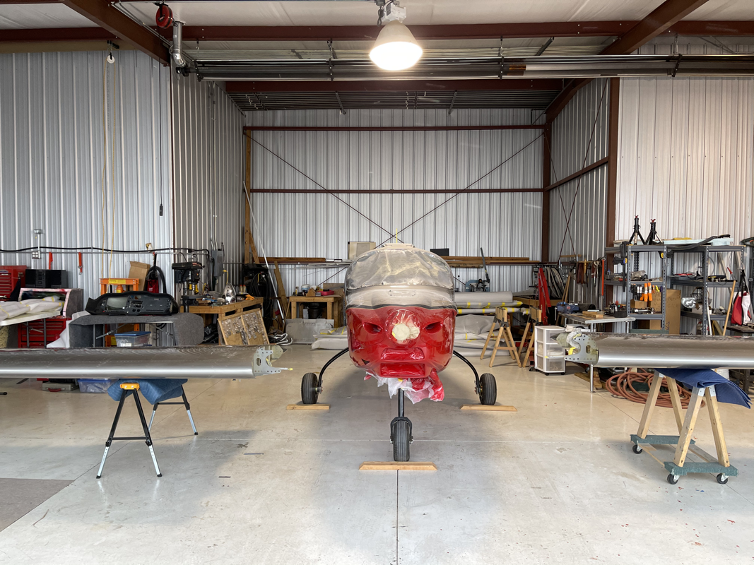
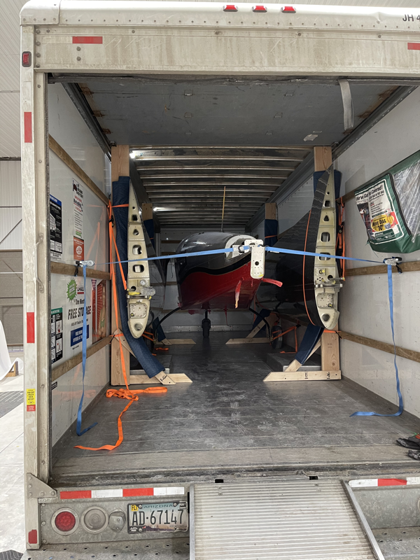
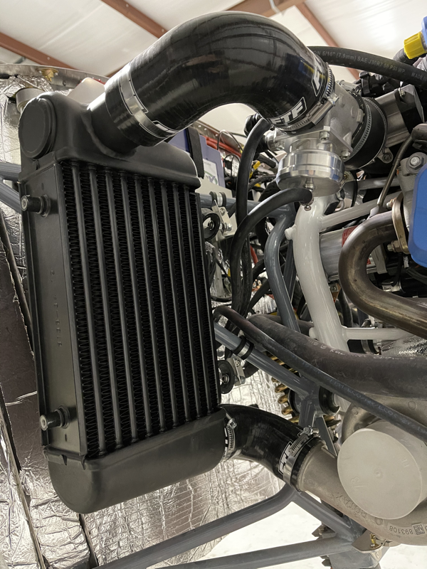
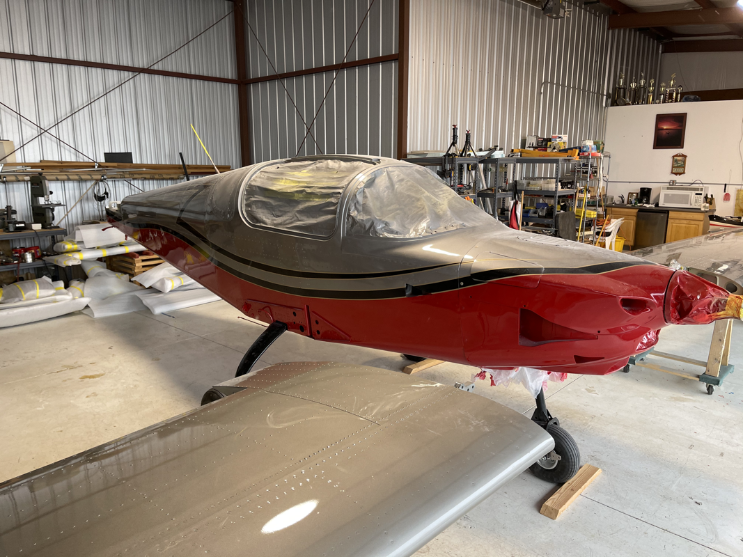
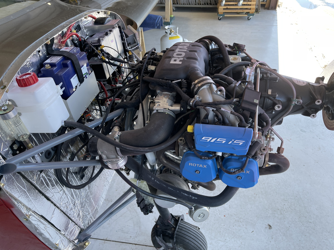
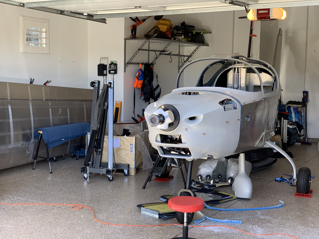
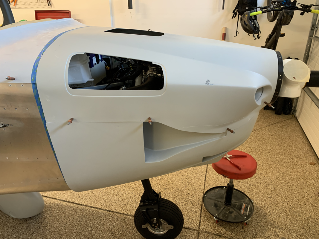
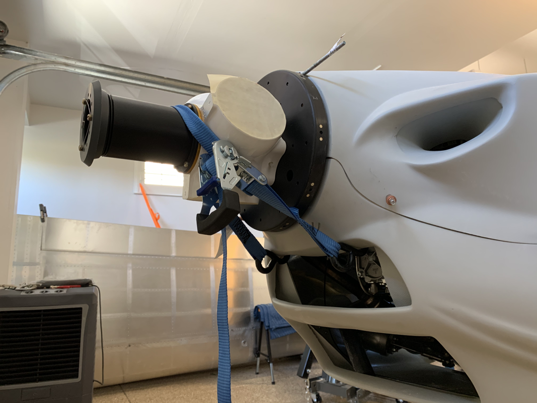
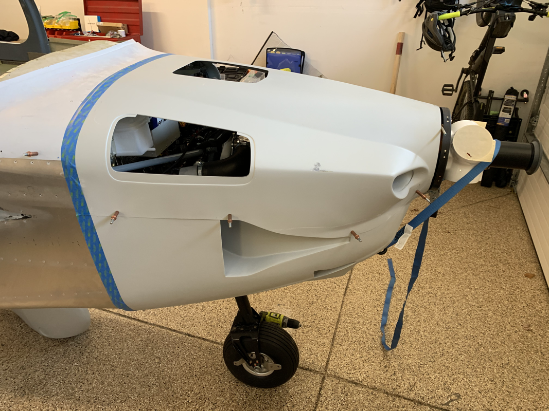
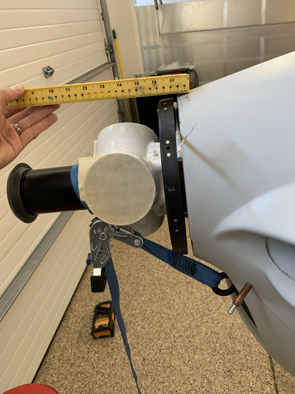
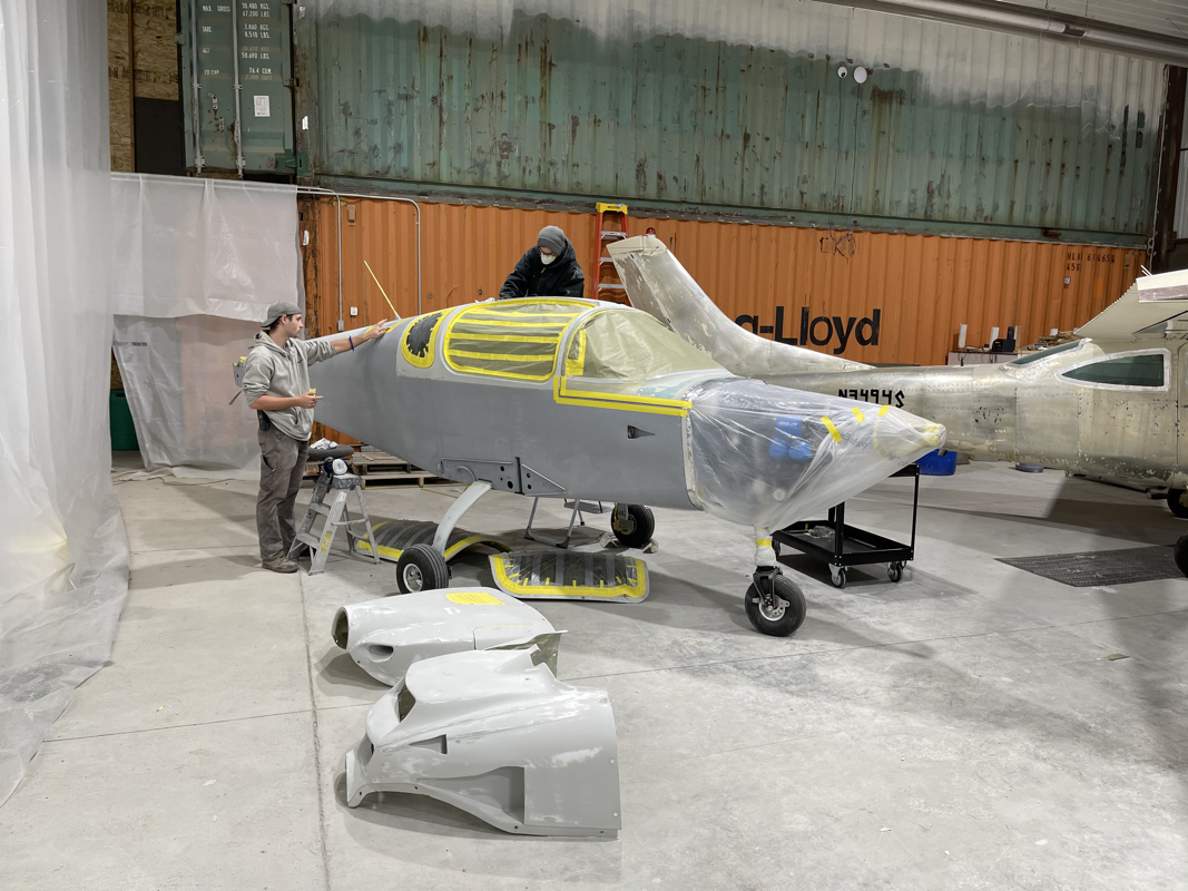
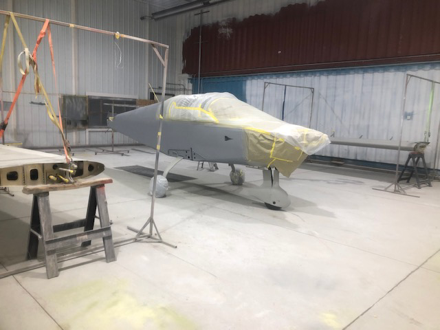
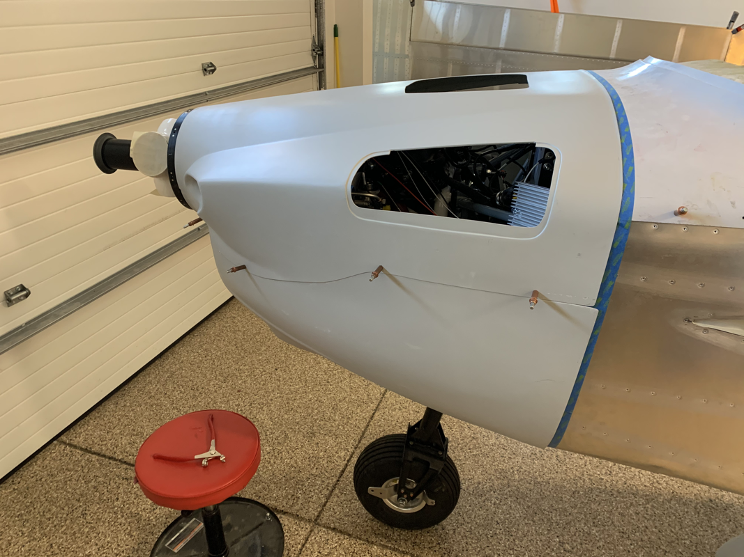
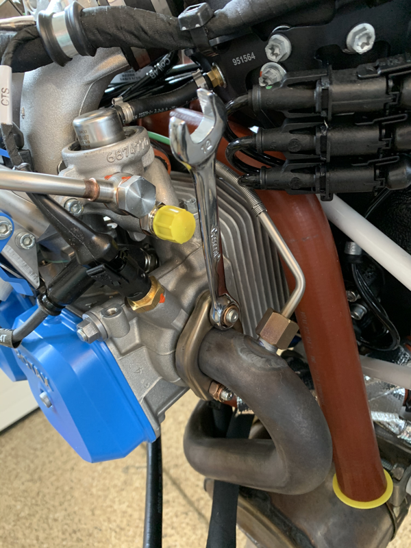
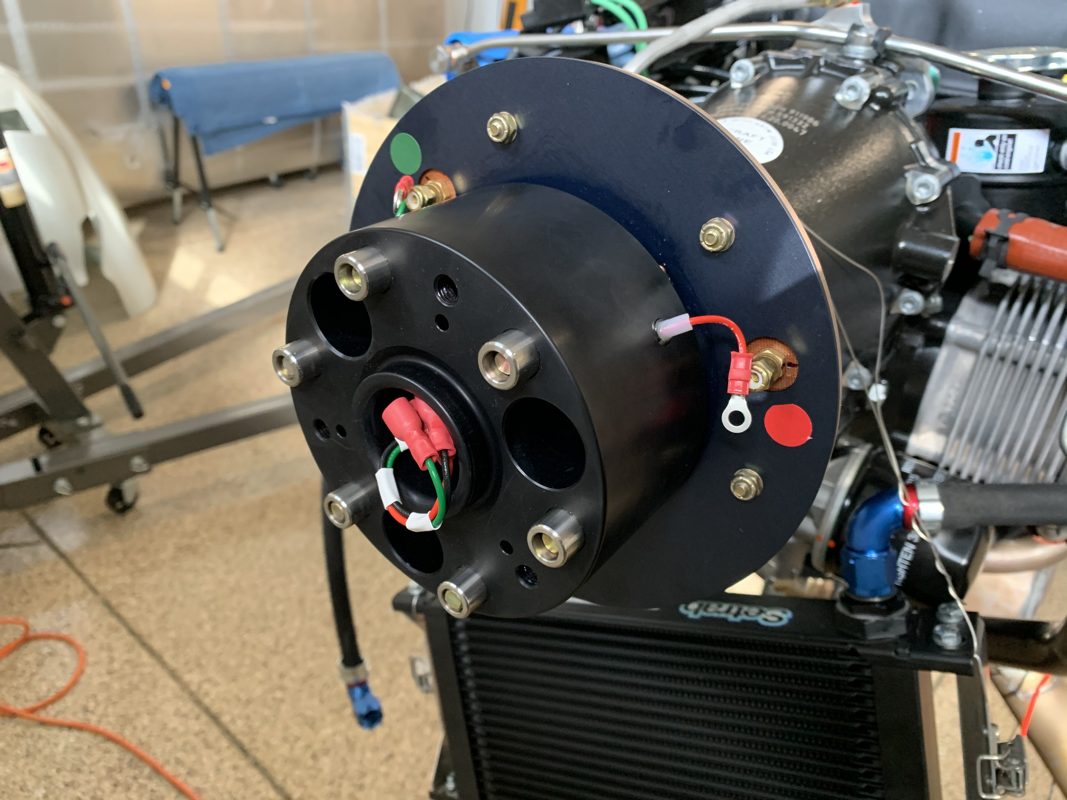
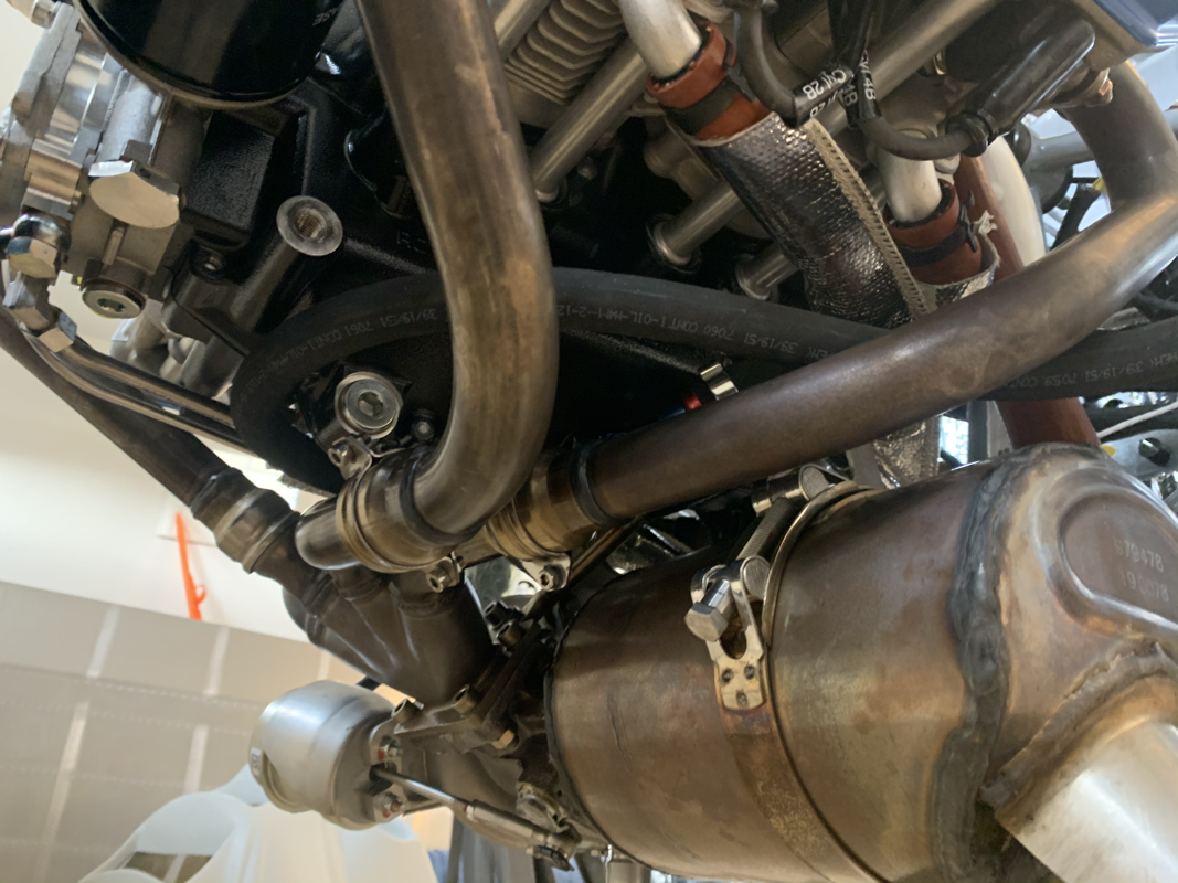
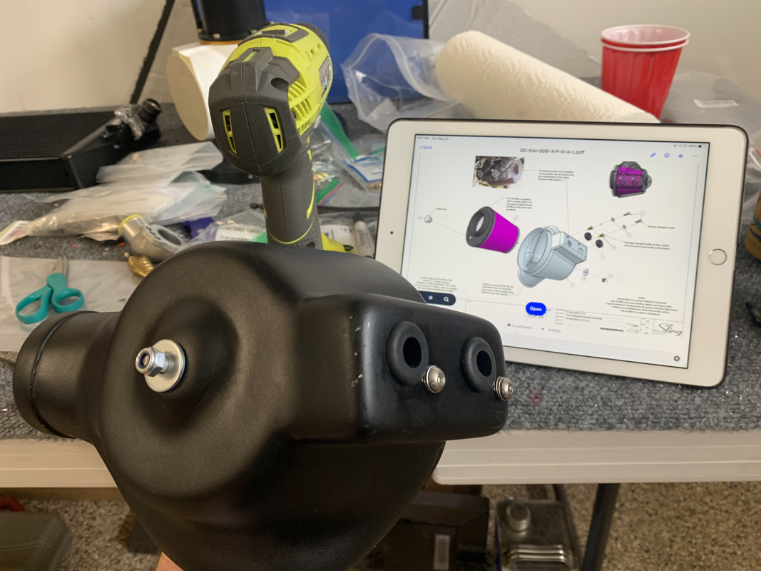
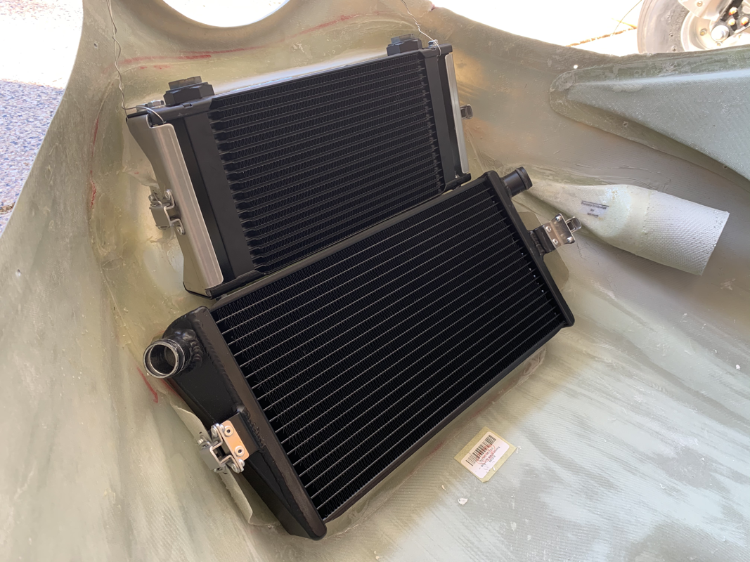
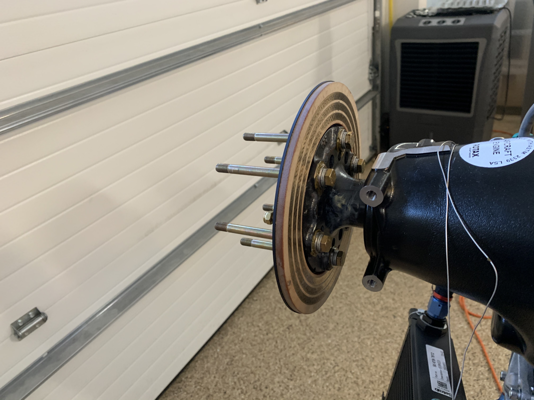
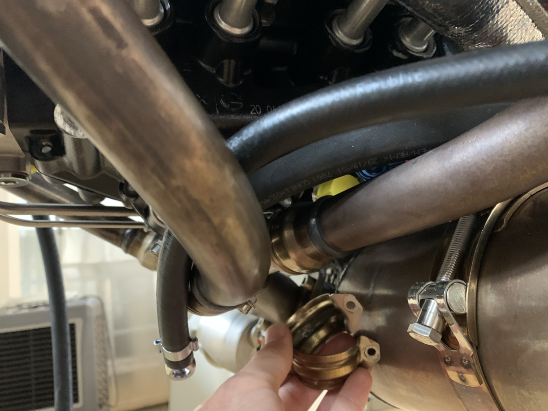
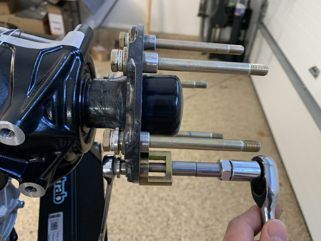
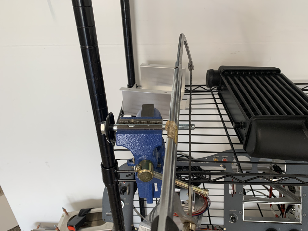
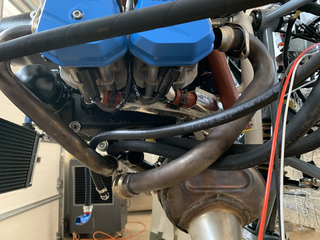
It feels great to finally see the engine mounted! Starting to feel like a real plane. Before mounting the engine, I wanted to revisit the nose wheel movement. It was still a bit stiff and took a few pounds of force to move it. I was thinking I don’t want the rudder to stick during flight, so it was timely there was a discussion on the Sling Builder’s Facebook group on the issue. The idea is to take a 2” dowel, about the same size as the nose wheel, sand it down a bit so you can staple some sandpaper to the dowel. From there, insert it into the assembly and rotate it until you get smooth turns. What a difference! From there, I torqued the nose gear assembly to the firewall and it was time for the big moment - mounting the engine! Note: the engine did come with a bolt, mounted to the fairing just above the turbo that is held on by a rivet. Be sure to drill that rivet out and remove the bolt, it’s only used for mounting to the shipping crate. Once the engine was mounted, I started assembling the oil hoses. It’s nearly impossible to get them on without any loosening. To help with that, I just put one end in boiling water for a minute or so and then lubricated the barb and hose with some oil. Be sure to slide it on in one quick movement.. it’s really hard to get the hose off once on the barb.. trust me. ;-) The intercooler assembly is pretty straight forward, just connect the hoses and mount it in the approximate location. Next up, mounting the propeller and fitting the cowling. This week I focused on fixing things I made mistakes on or that were quick and easy.
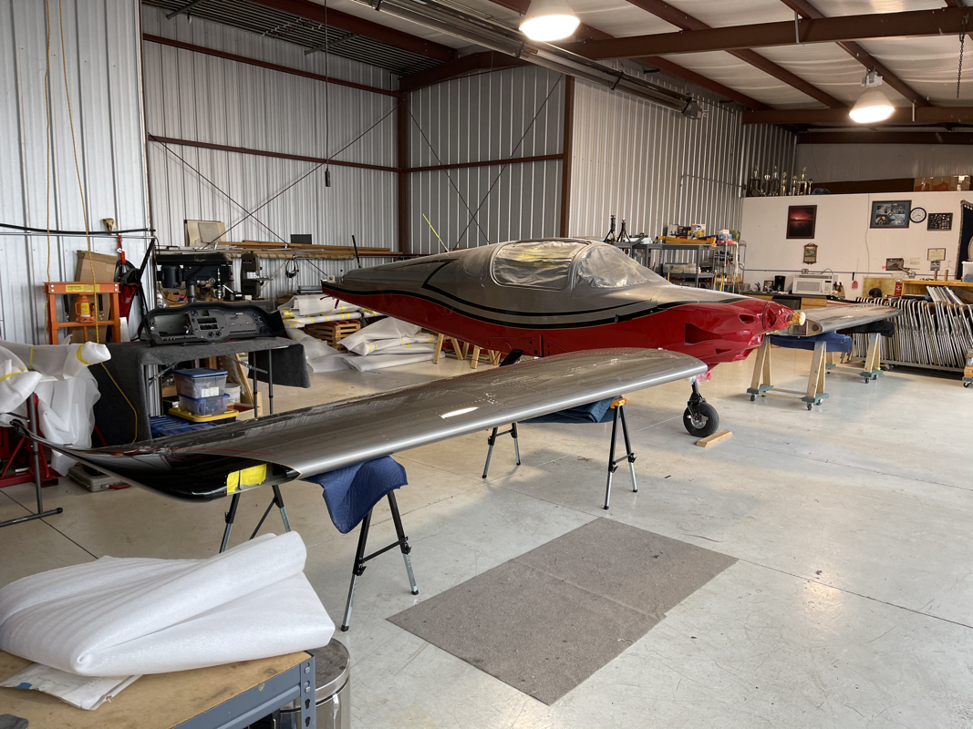
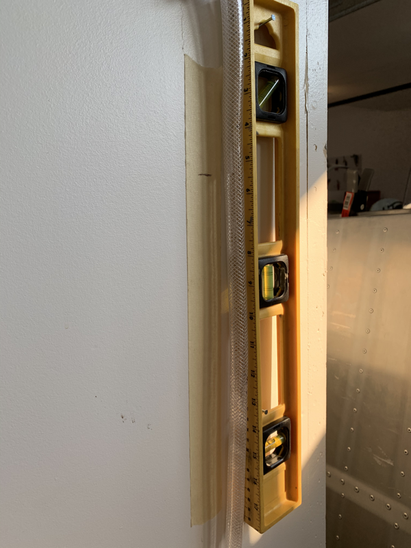
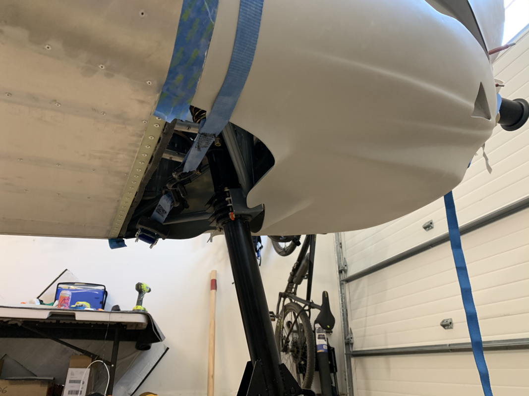
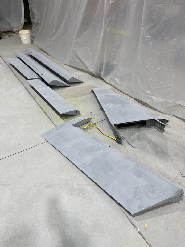
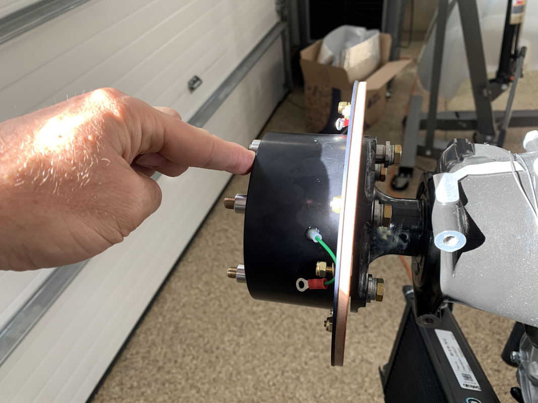
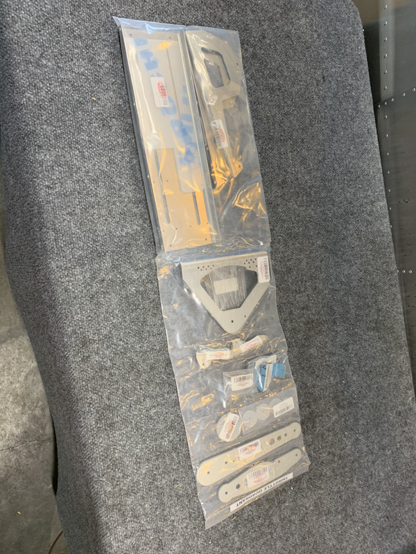
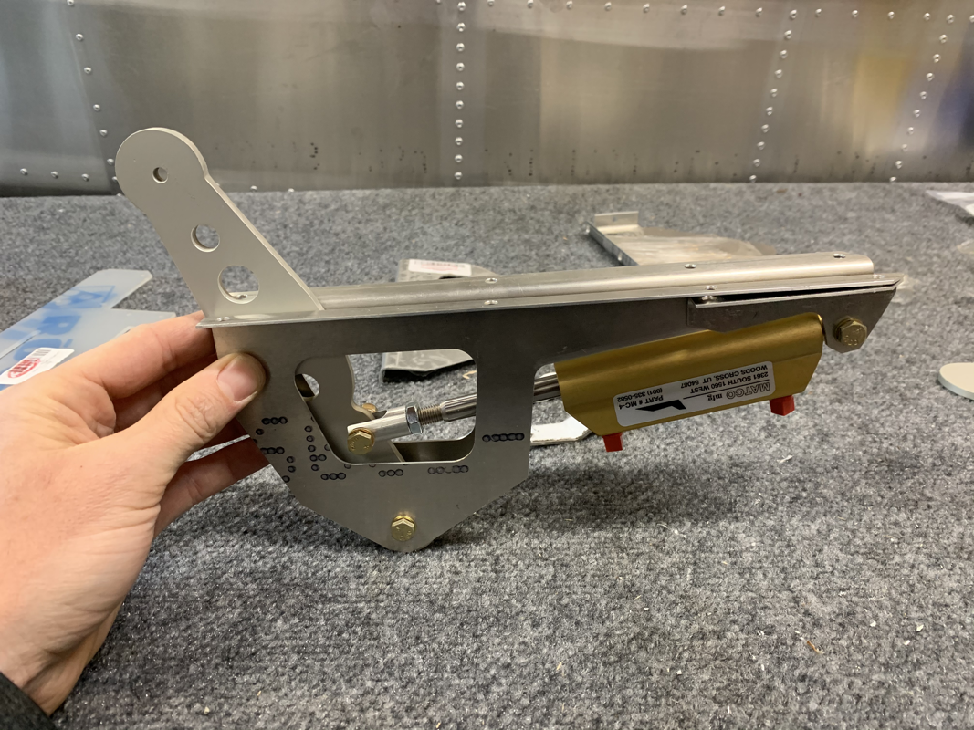
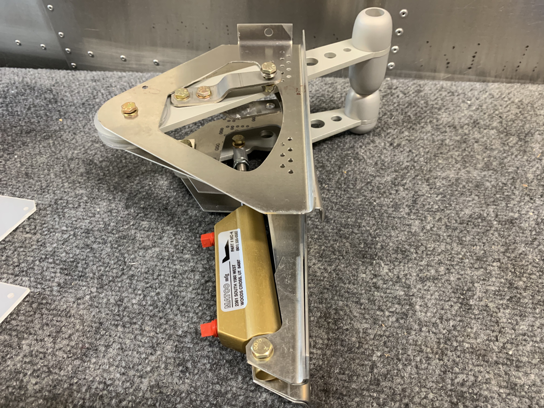
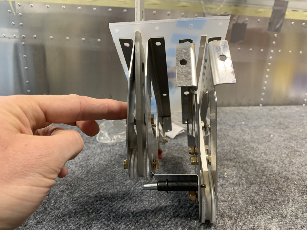
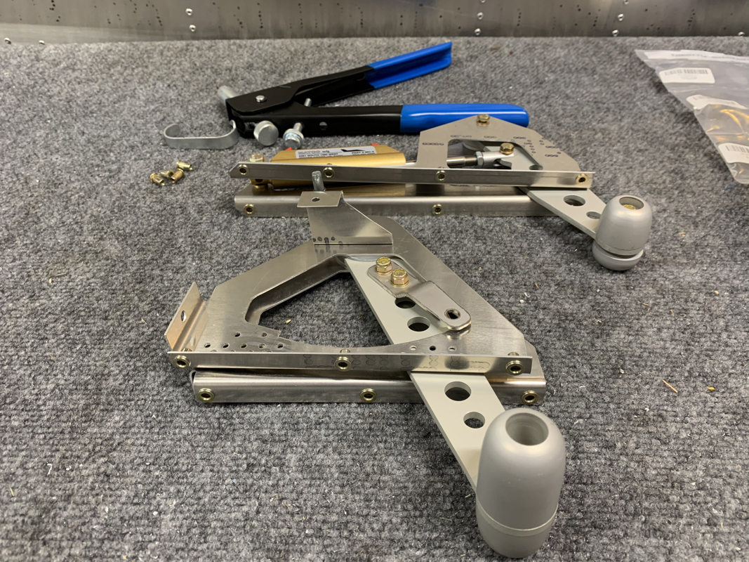
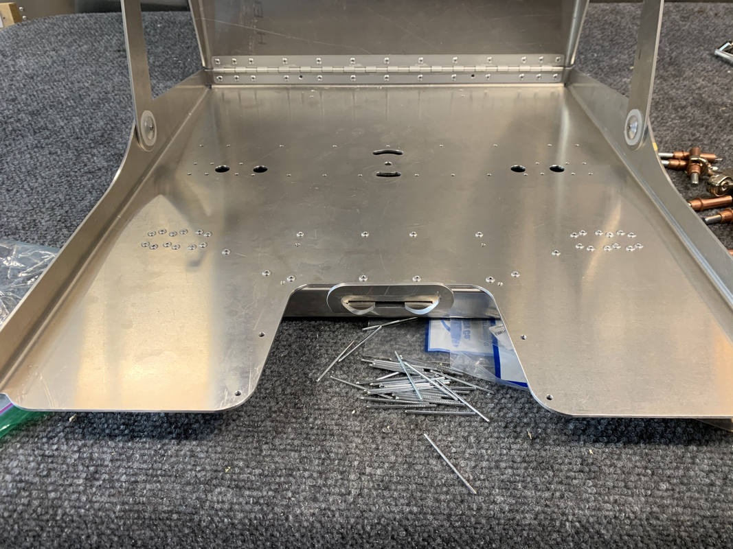
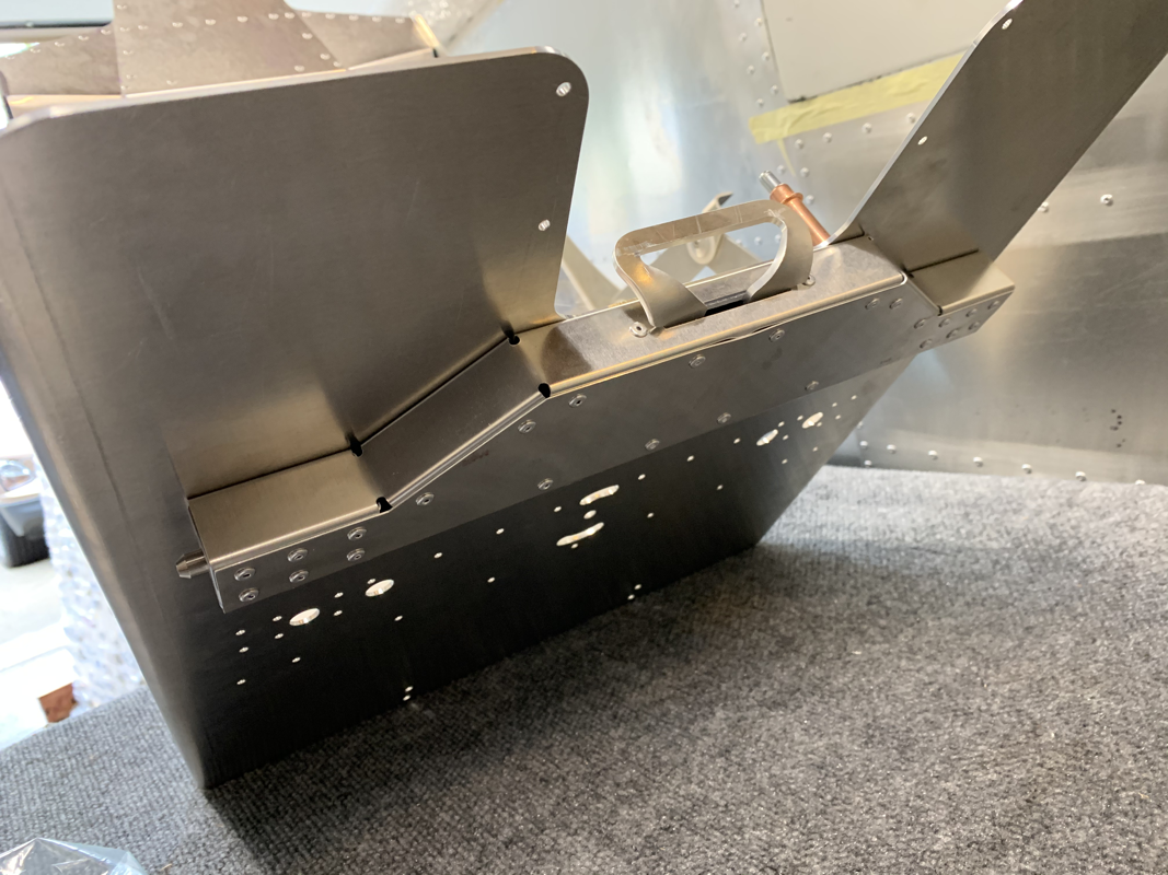
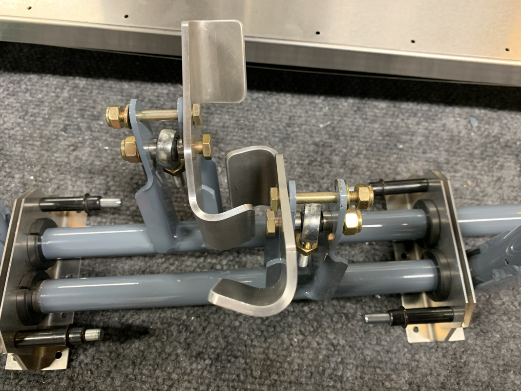
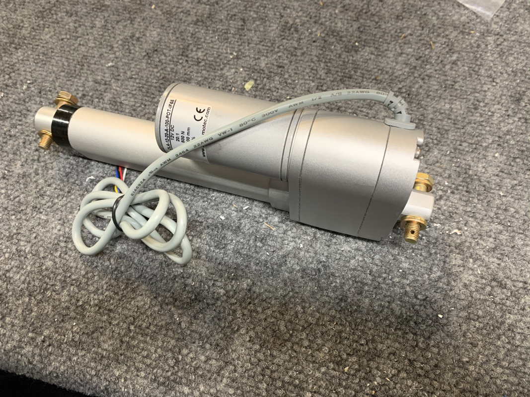
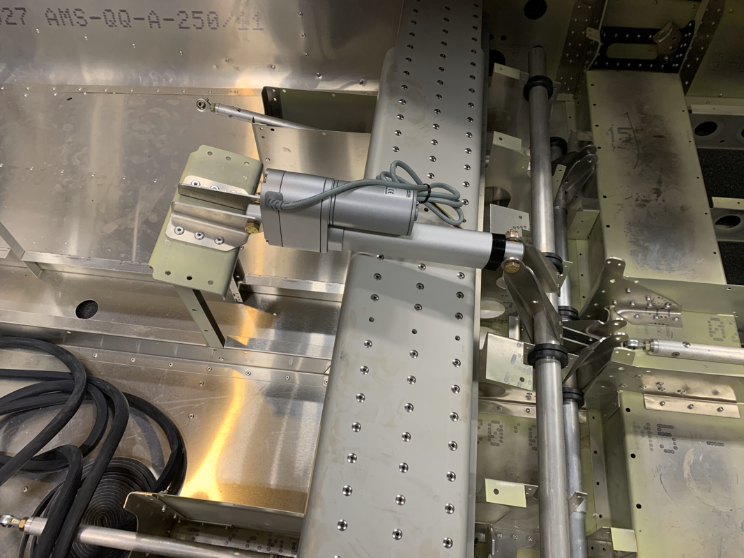
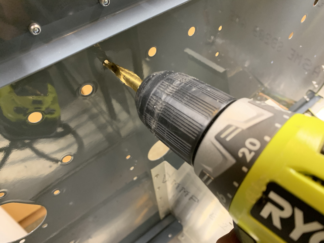
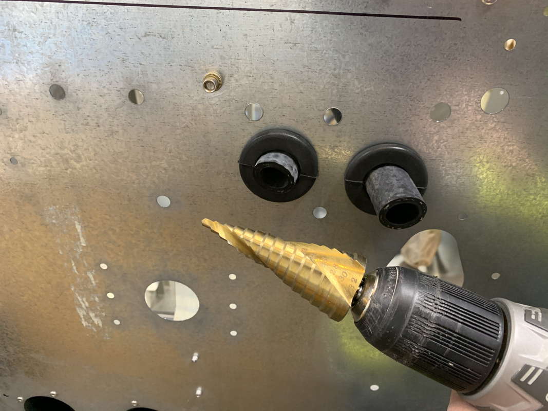
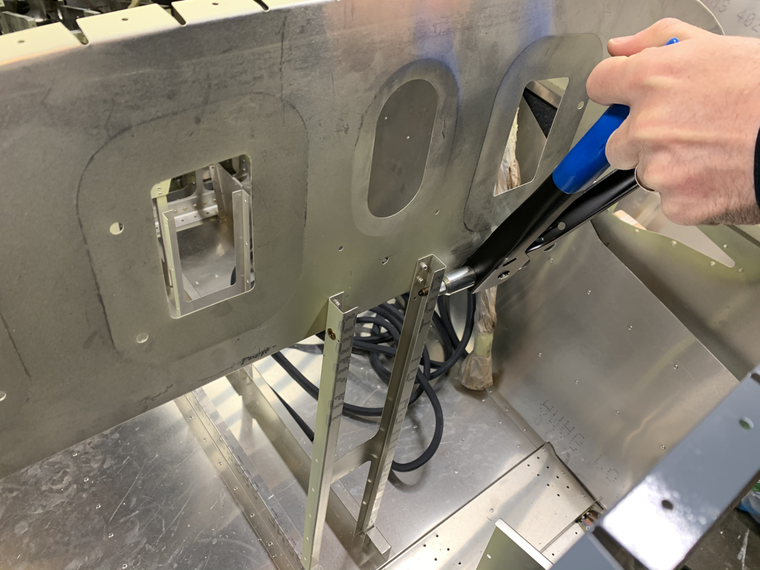
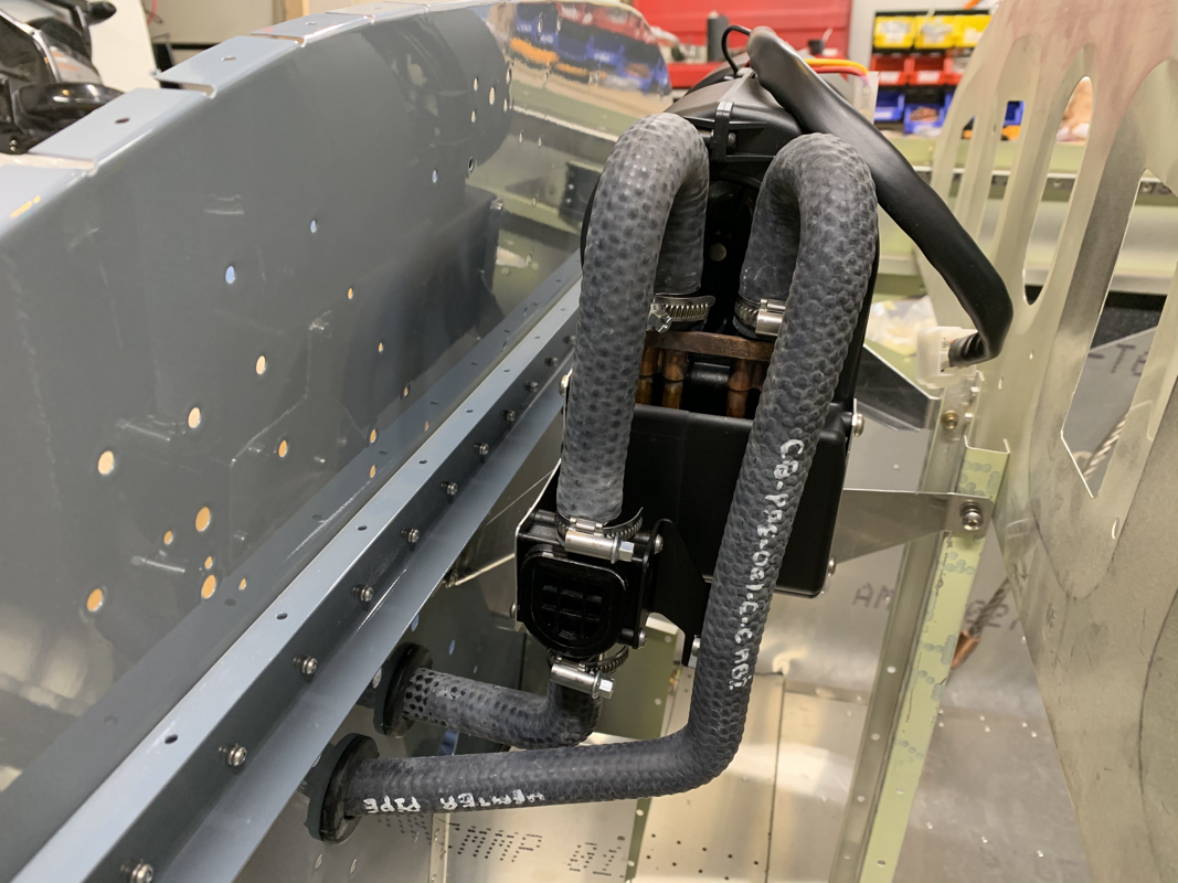
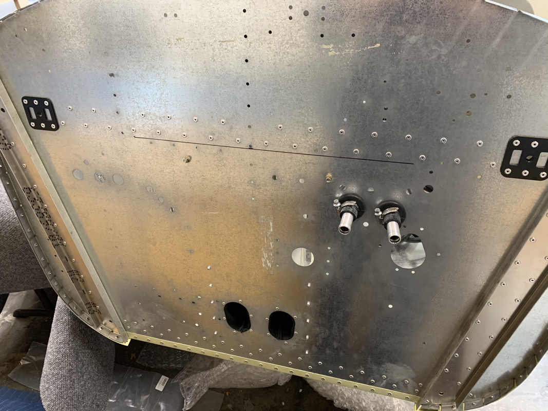
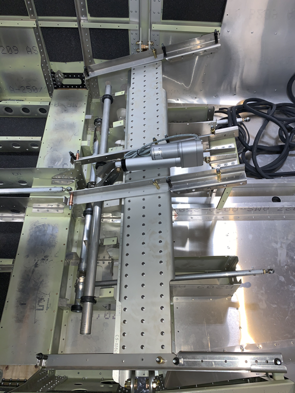
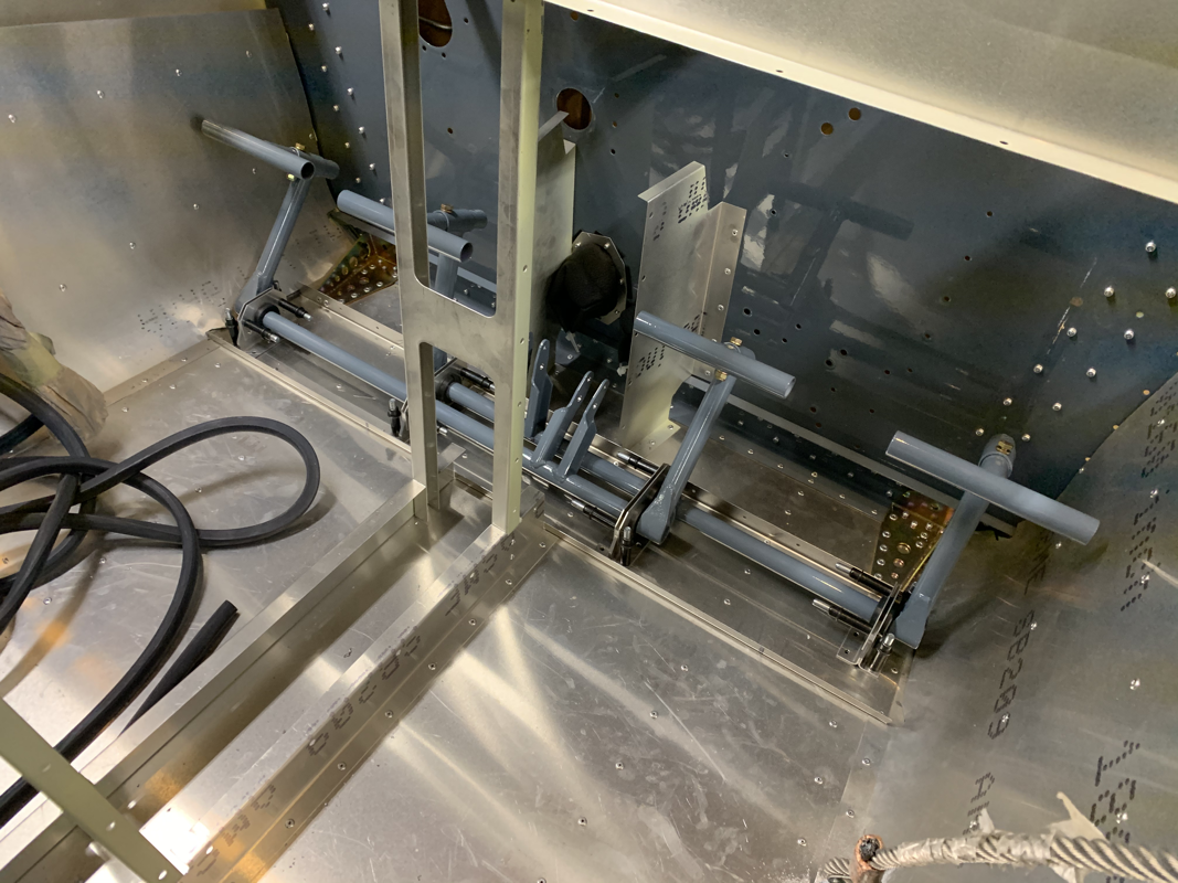
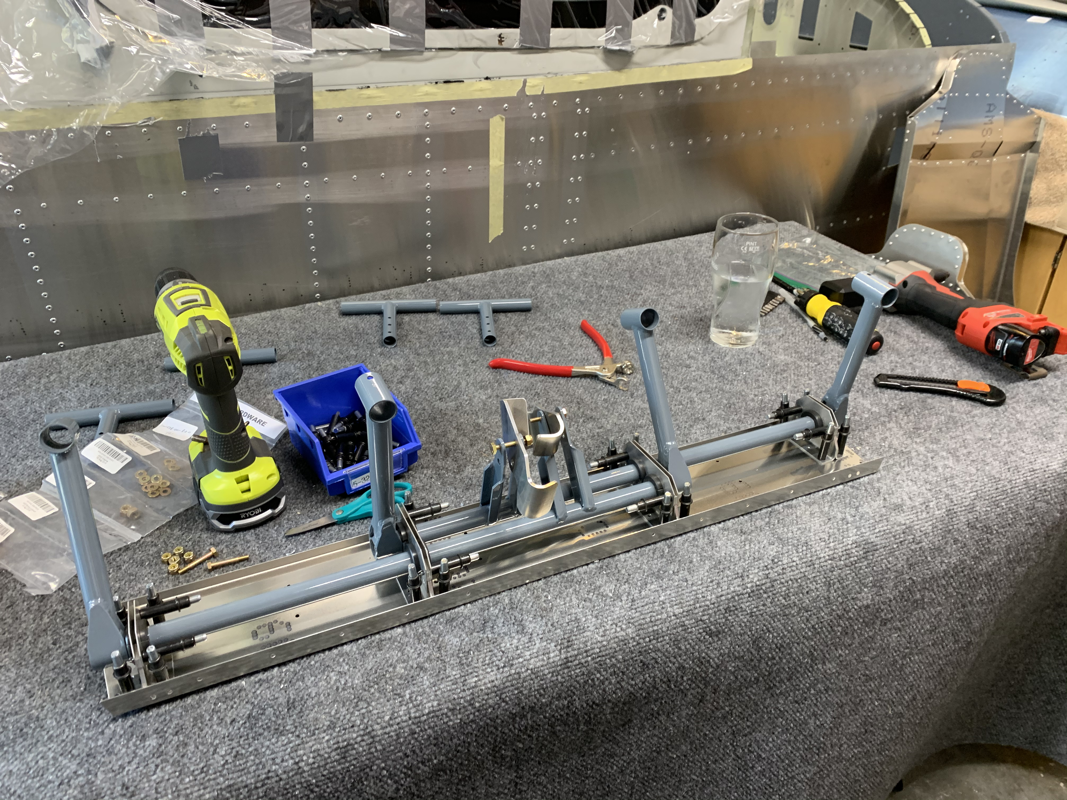
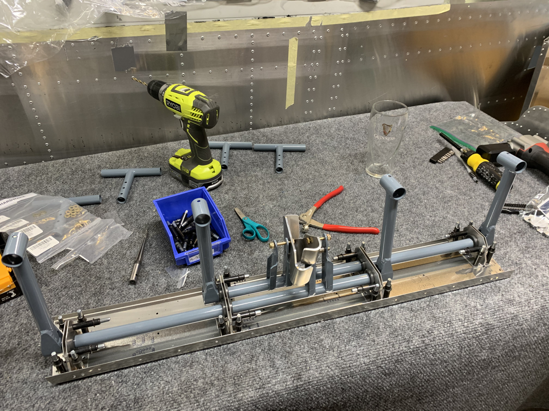
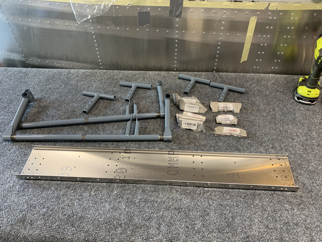
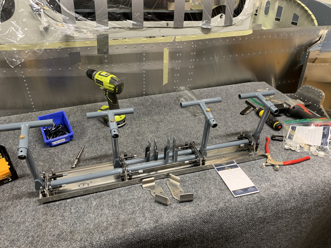
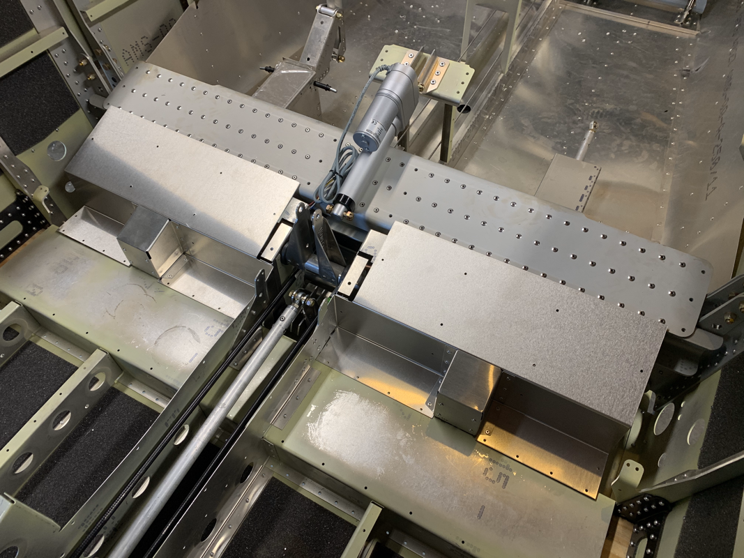
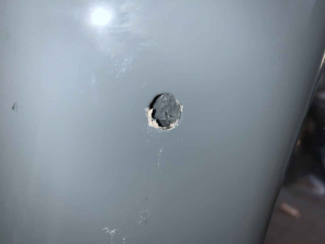
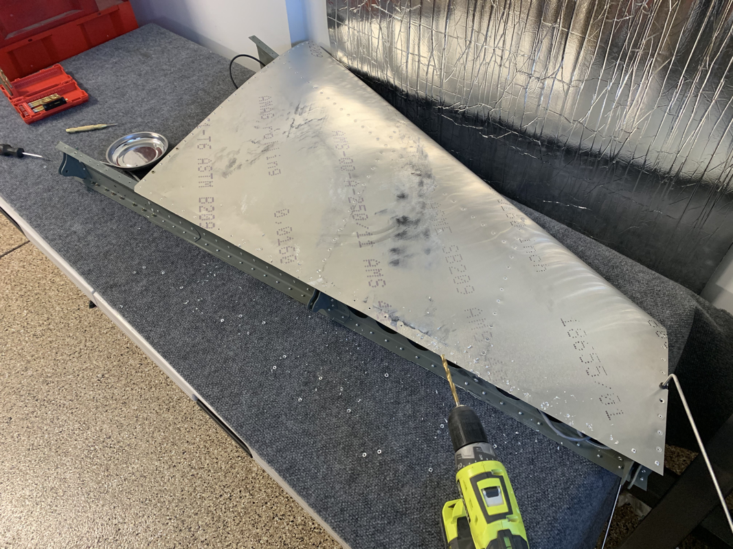
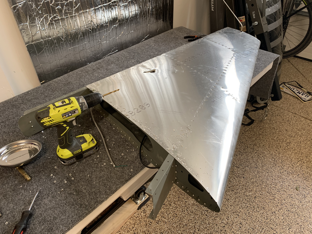
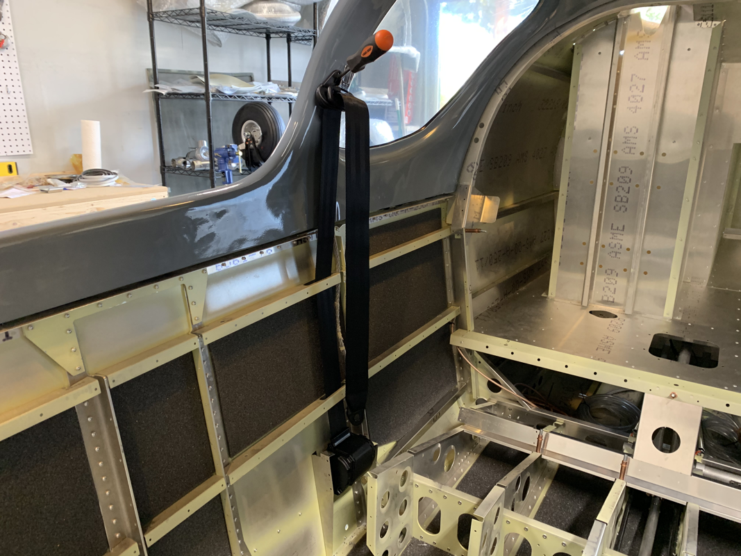
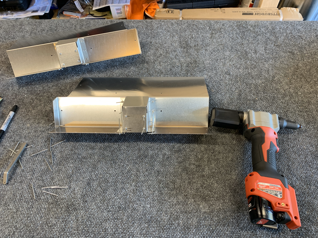
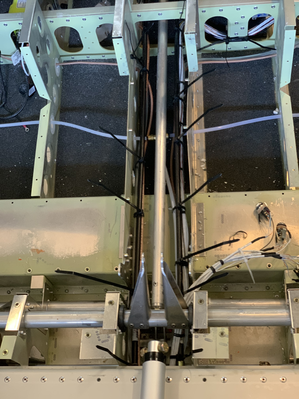
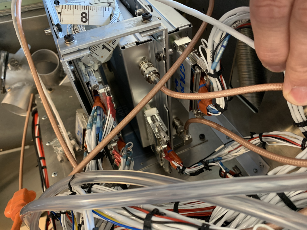
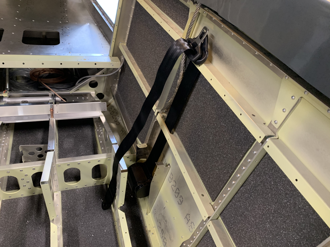
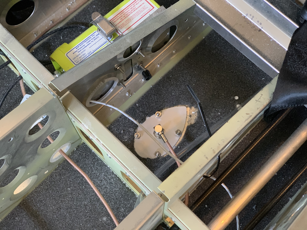
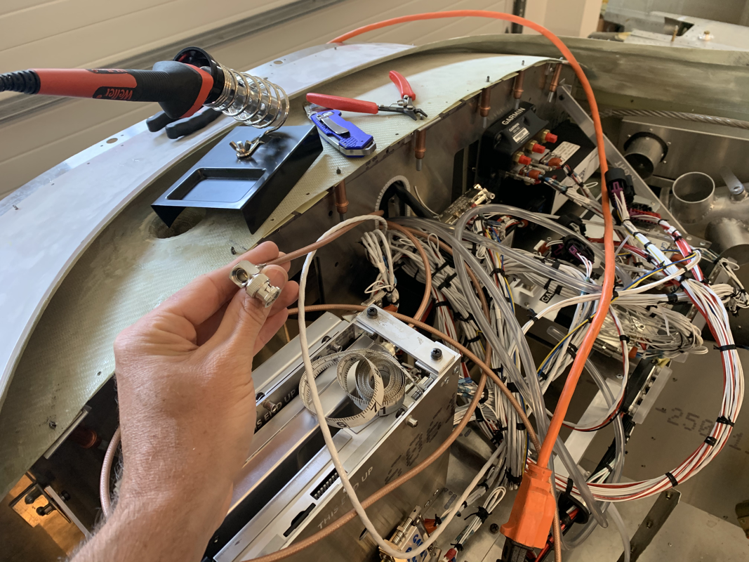
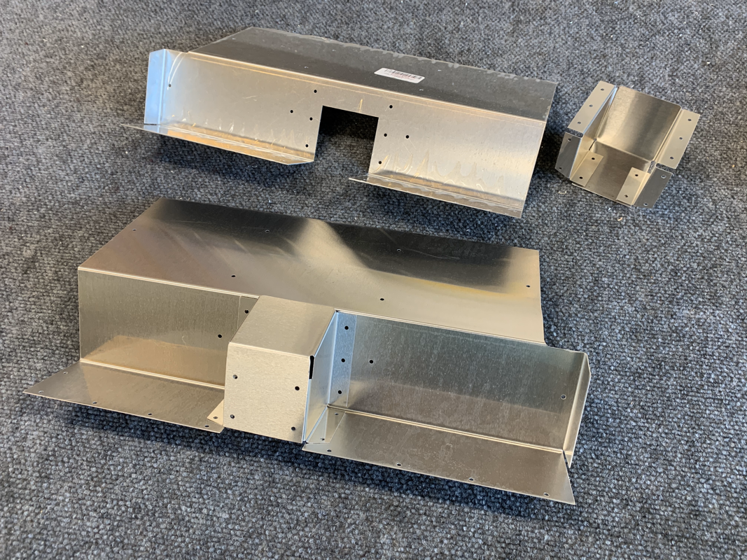
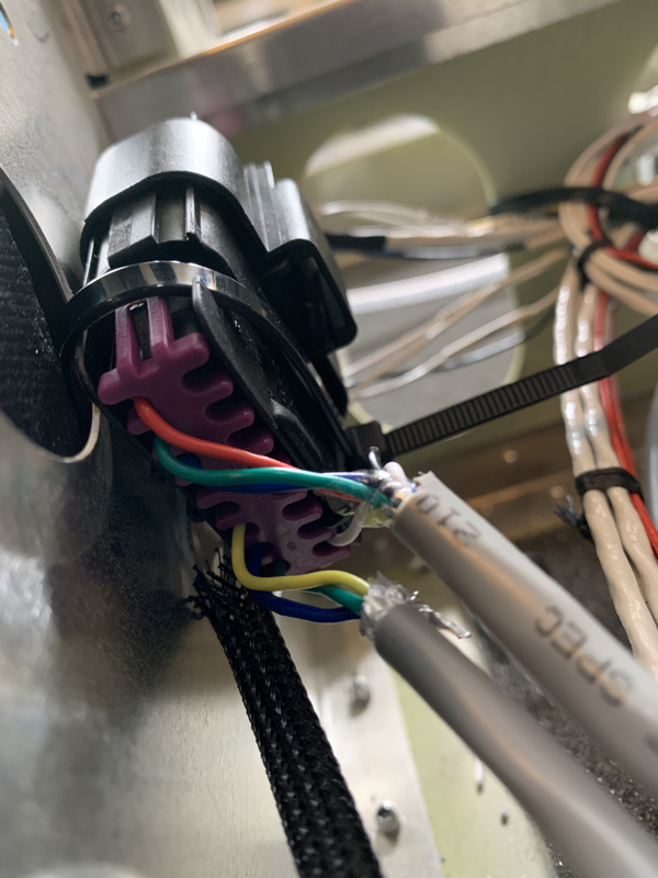
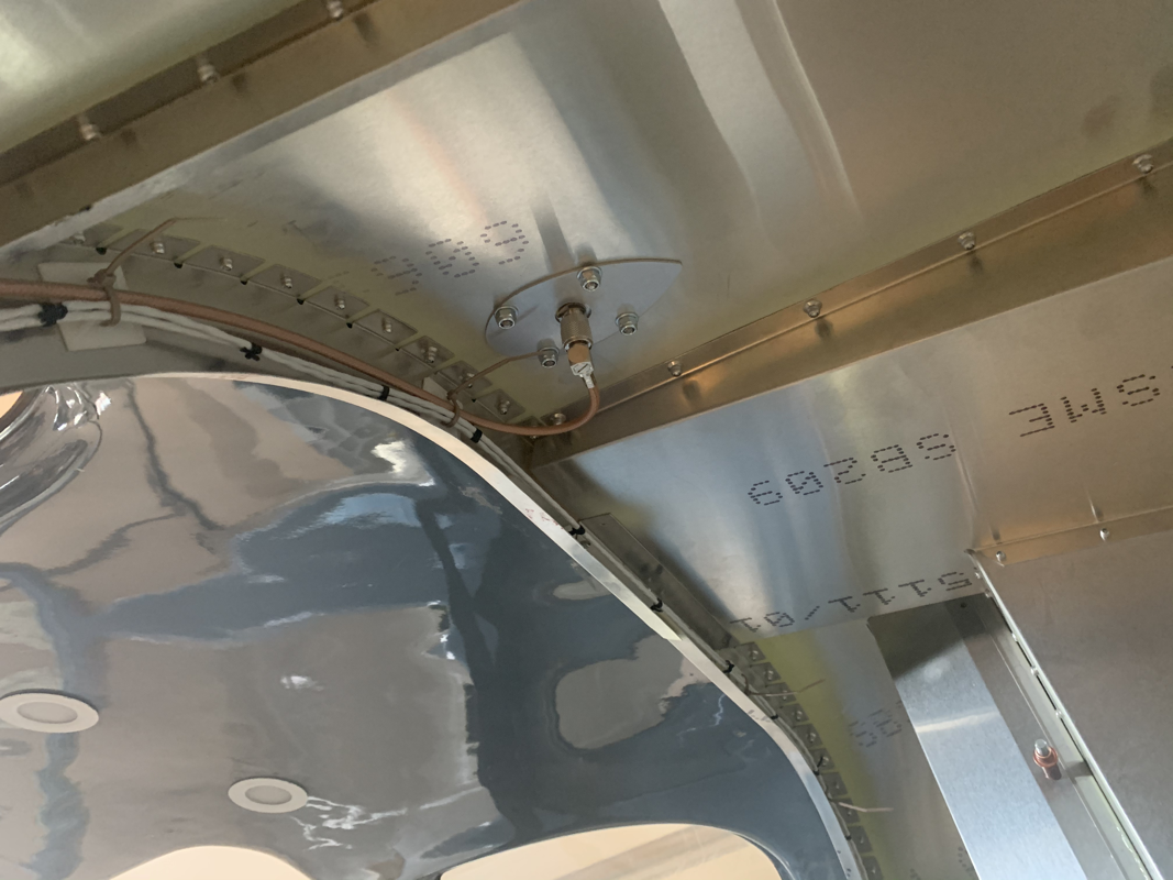
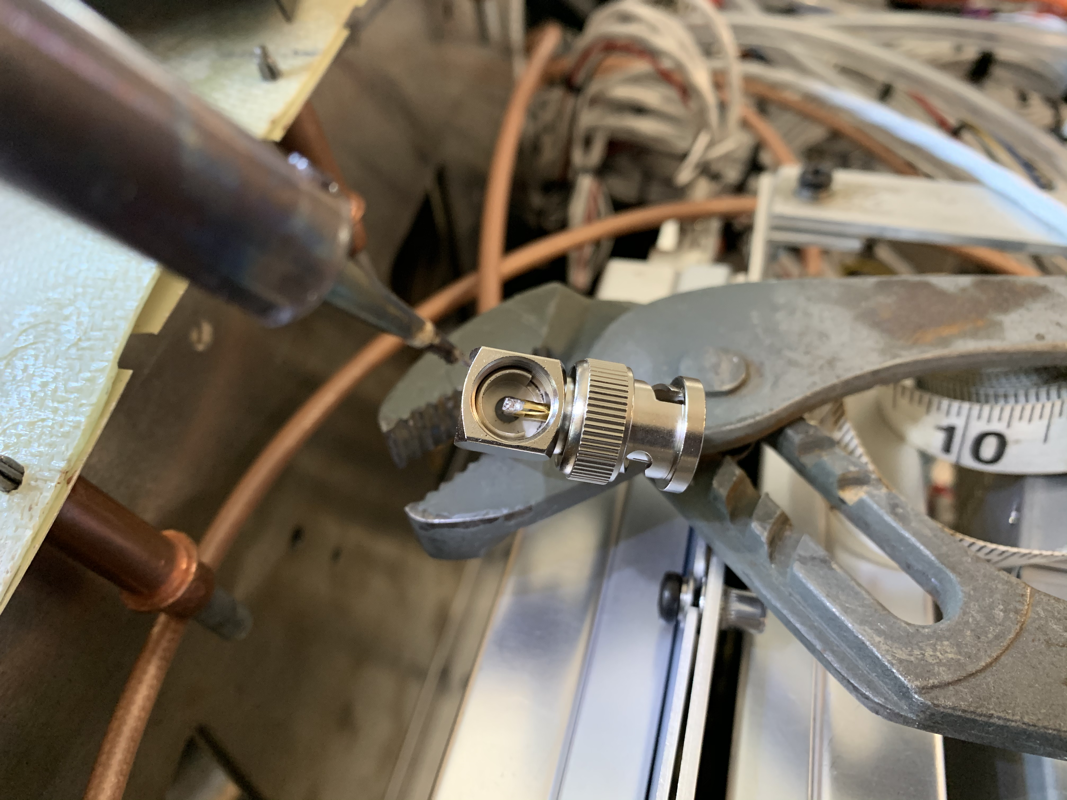
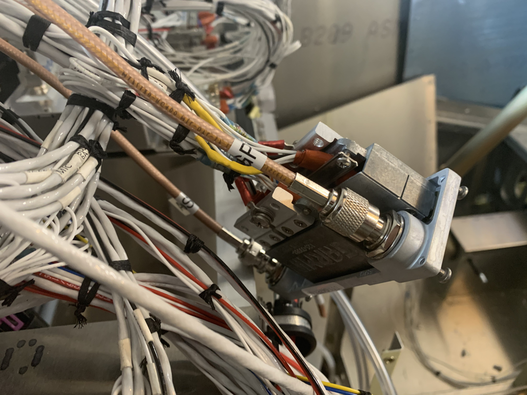
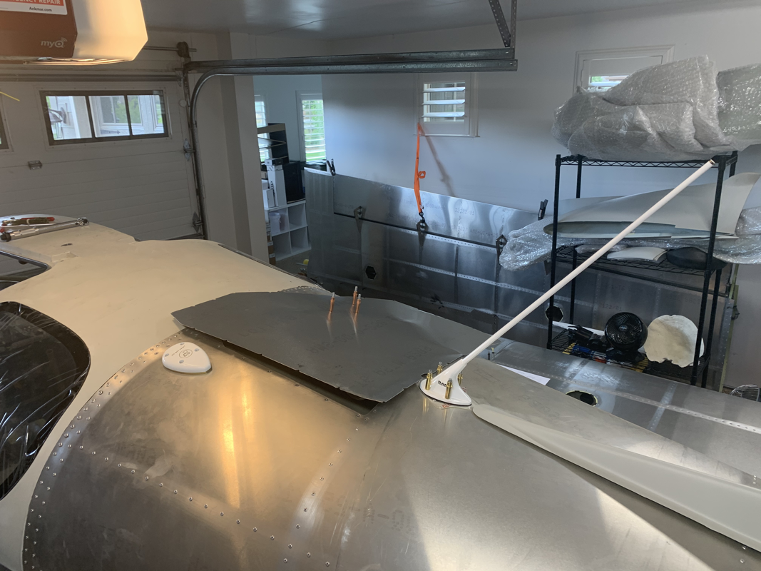
Phew! That was a lot.. looking forward to moving on to digging into the avionics a bit more next week! Working on some odds and ends this week as I’ve had several items ready to be completed. Ideally I’d like to work on a single item and see it through to completion, but I either have a missing part, tool, problem to figure out, etc so I find something else to work on to move forward. I received a shipment from TAF recently that had the autopilot pushrods, some misc parts and my joystick control assembly. Unfortunately, they only sent one, so I’m still waiting on the other. At least now I can finish up the control pushrods and test it out! I finished up the main landing gear, so it’s all ready to mount. I went with the AN4-26A bolt they provided and just added 2 washers under the head of the bolt to make sure the bolt ends don't hit the wheel spat. I now just have to lift the plane and see how it fits. However, I'm going to have to flip the plane around in the garage with the nose wheel on and angle it for it to fit in the garage. I've also attached the rudder springs. I had to get a flexible drill bit to enlarge the holes for the M5 Rivnut as the luggage floor prevented the drill from fitting. The nose gear took some time to get unbined. The vesconite bushing on the top of the gear was the main culprit, so I took some sandpaper and started sanding by hand and test fitting often. Once I was able to freely twist the bushing, I used a smoother grit to make sure the bushing was contacting the metal with a smooth surface. Next up I'll be finishing up the control torque tubes and connecting the pushrods.. more to come! I'm quickly running out of inventory on my shelves! I'm kinda glad I pulled the trigger on the avionics, I just hope it doesn't take the whole 3-4 months of lead time to get everything in. That would mean some down time, unfortunately. I started working on the Throttle and Brake Controls to get them mostly assembled. I am keeping the center console channel undone for a while so I can run wires, but I figure I might as well get parts pre-assembled and out of bags. The brake and throttle went together easily, but it looks like I'm missing some parts. Of course they are small things, like one Castle Nut and one Bolt Bushing used for the throttle cable. Speaking of missing parts, I did get a shipment in from Aircraft Spruce with some bolts I needed to finish up the front seat and the rudder pedals! Nice to finally check those off my list. With the goal of clearing some inventory from the shelves, I picked up some components that were relatively quick to install. The flap actuator is held on by two bolts, so I placed it in there and temporarily secured it. I am having some friction issues on the control tubes while secured in the frame.. will need to trim the brackets that hold the bushings a bit to make them move without much effort. Saving that exercise for another day. For the heater, I measured and drilled the mounting rivnut locations. Since I was drilling through the firewall, I measured and checked at least 5 times! Didn’t want an errant hole to plug up.. Drilling the 32mm hole for the bushings was made easy with a metric step drill bit I found on Amazon. Once done I just pulled the hoses through and secured the hose connector with some hose clamps. From there, I moved on to the front seat rails. Only a few components there, so I secured in place with clecos. I’ll be getting the missing rudder pedal bolts from Aircraft Spruce tomorrow, so I figure I cleco them in place. I’ll connect the pushrods and rudder cables as soon as the bolts arrive. The Rudder pedals came with relatively few parts, so I thought this would be a quick one. Unfortunately, I’m missing some AN4 bolts that hold the stops in place. While I wait for that, I’ll be priming the bottom plate and working on removing any friction from the bushings. There were 2 points where there was still some adhesive left from the tape when these were powder coated. Some acetone made some quick work of getting rid of that and there was much better movement in the pedals. I was able to spend some time finishing up the rudder. The main hurdles that took time were fitting the rudder tip and placing the VOR Antenna on the top rib of the Vertical Stabilizer. Placing the light was pretty straightforward, but when I went to fit the rudder tip, it was a bit too long. I asked Phillip how he went about it and he said to just trim the back a bit to get a snug fit. After that, it was just match drilling the holes and countersinking the first 7 holes. I saw a note in Phillips blog to pay careful attention to the number of countersink holes since the instructions say do the first 9, but there are only 7 done on the skins. Once things all lined up, I went ahead and soldered the light wires and wrapped them with heat shrink. I added some wire protection to the part of the cable that is exposed outside of the skins. I did need to use the angled pop rivet tool on the bottom of the rudder, as it was pretty close quarters to the plate. I did a final check of the alignment and it was still straight. Feeling good to be almost done with the Empennage! Now to skin the Vertical Stabilizer to finish things up! This time I did the cleaning, scuffing, degreasing and priming of the Vertical Stabilizer and Ruder in a batch. This seemed to speed things up since I already had everything prepared and lined up to use. I just had to make sure the parts were different enough that I could tell what goes where when it comes time to assemble it all! I did notice that the flange at the bottom of the rudder (Last Photo) does rub against the rib. It causes it to expand, leaving the skin to be uneven and would probably be an issue. Mike Black from Sling Central had also mentioned this issue and came up with a slight modification that seemed to work well and doesn't affect the structural integrity, so I'll be making the same fix. Overall, these parts are coming together a lot more quickly than the Horizontal Stabilizer and Elevator. Progress! Until, I ran out of 4mm x 10mm rivets. I'm also looking to be a bit short on the 3.2mm x 8mm rivets.. Perry from The Airplane Factory in Torrance, CA is sending some over and will pick things up from there. |
Archives
September 2021
Categories
All
|


 RSS Feed
