|
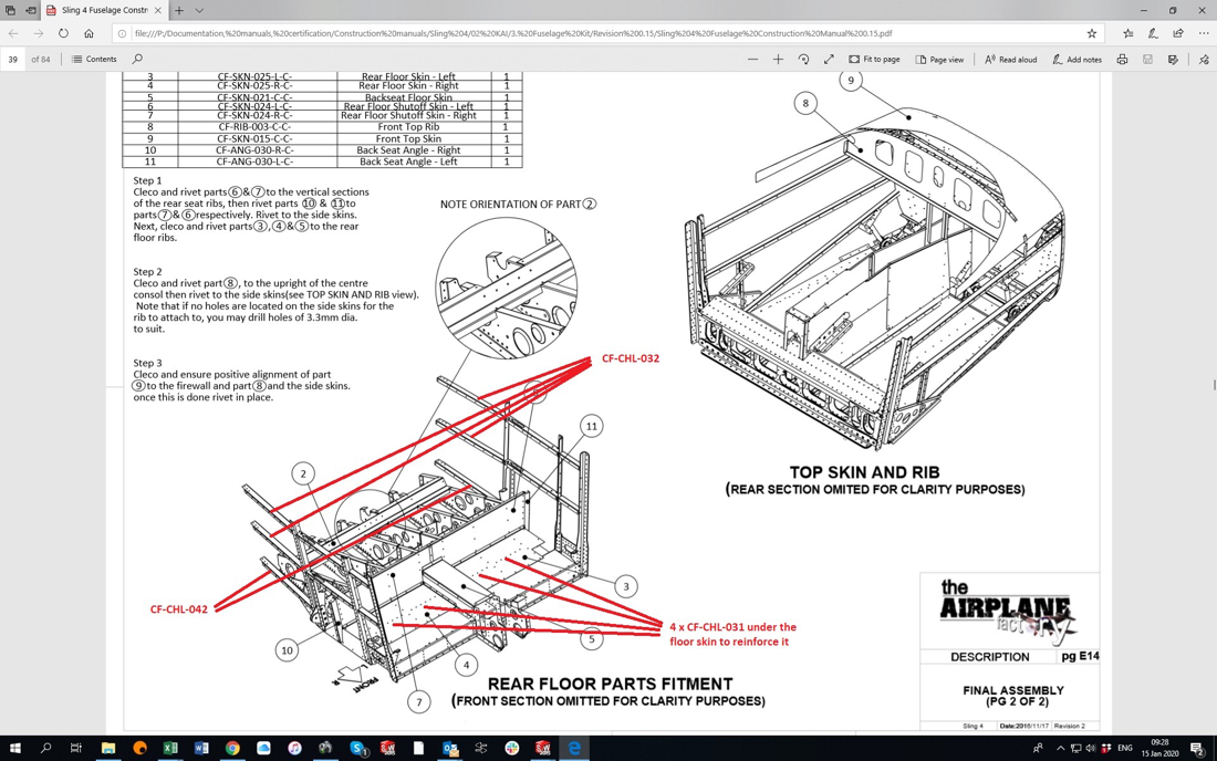
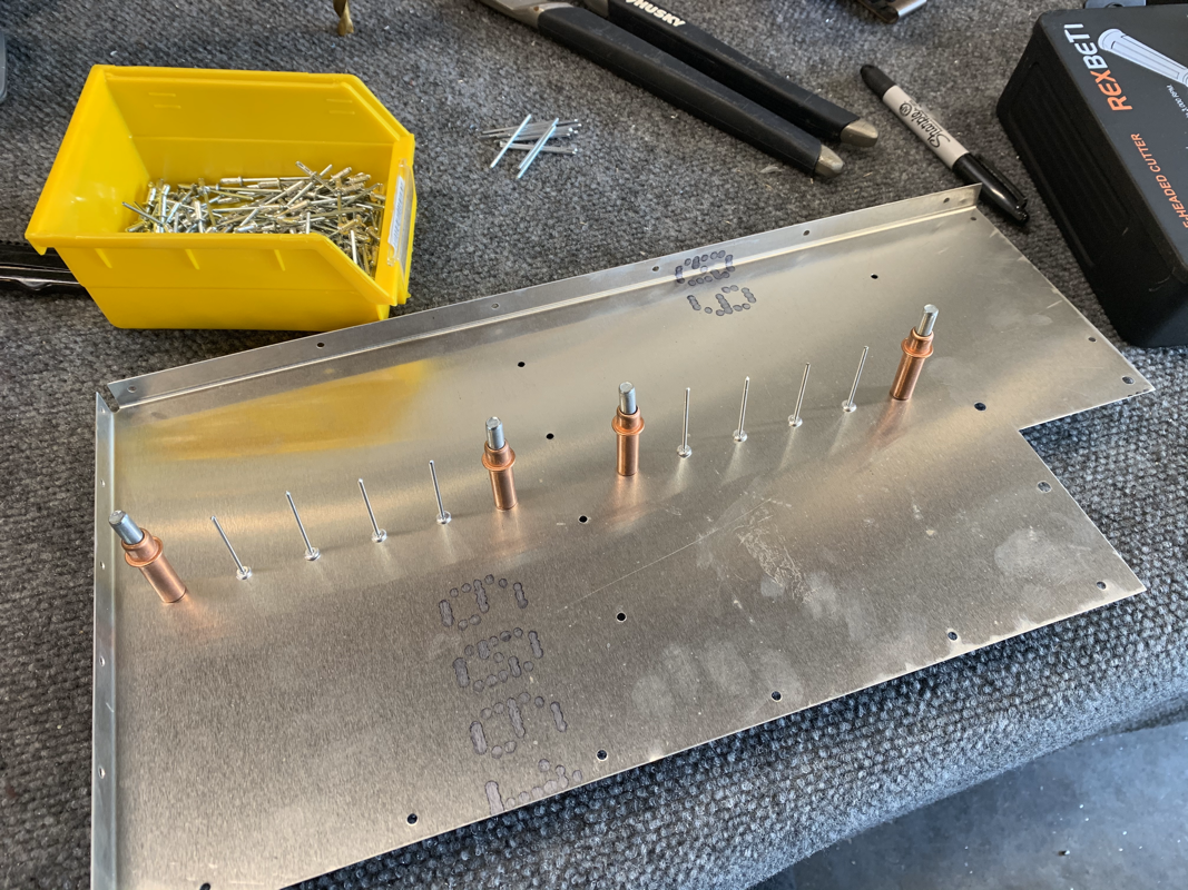
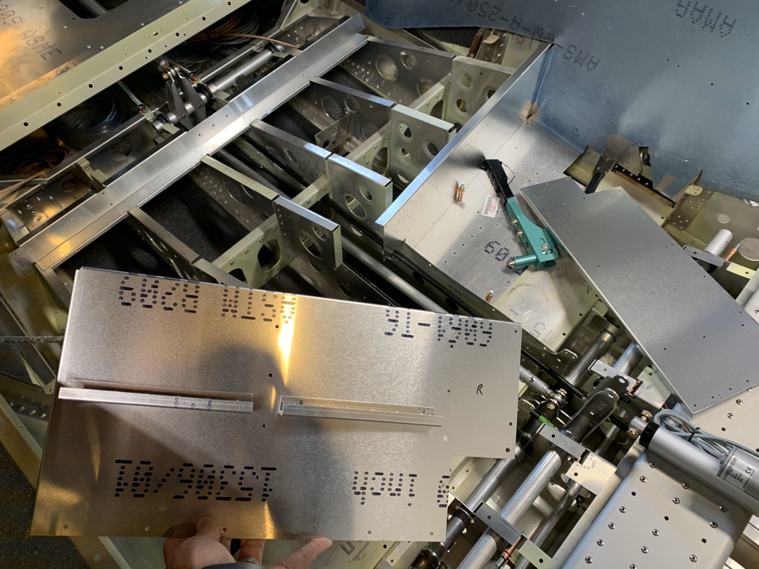
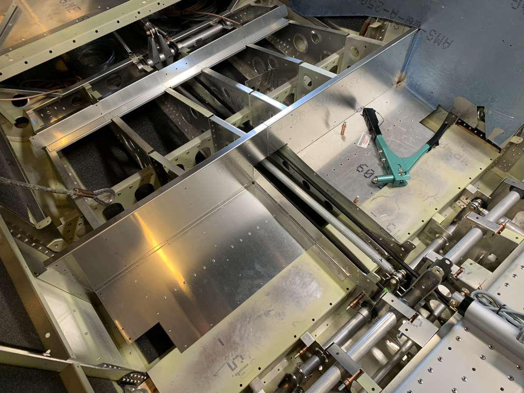
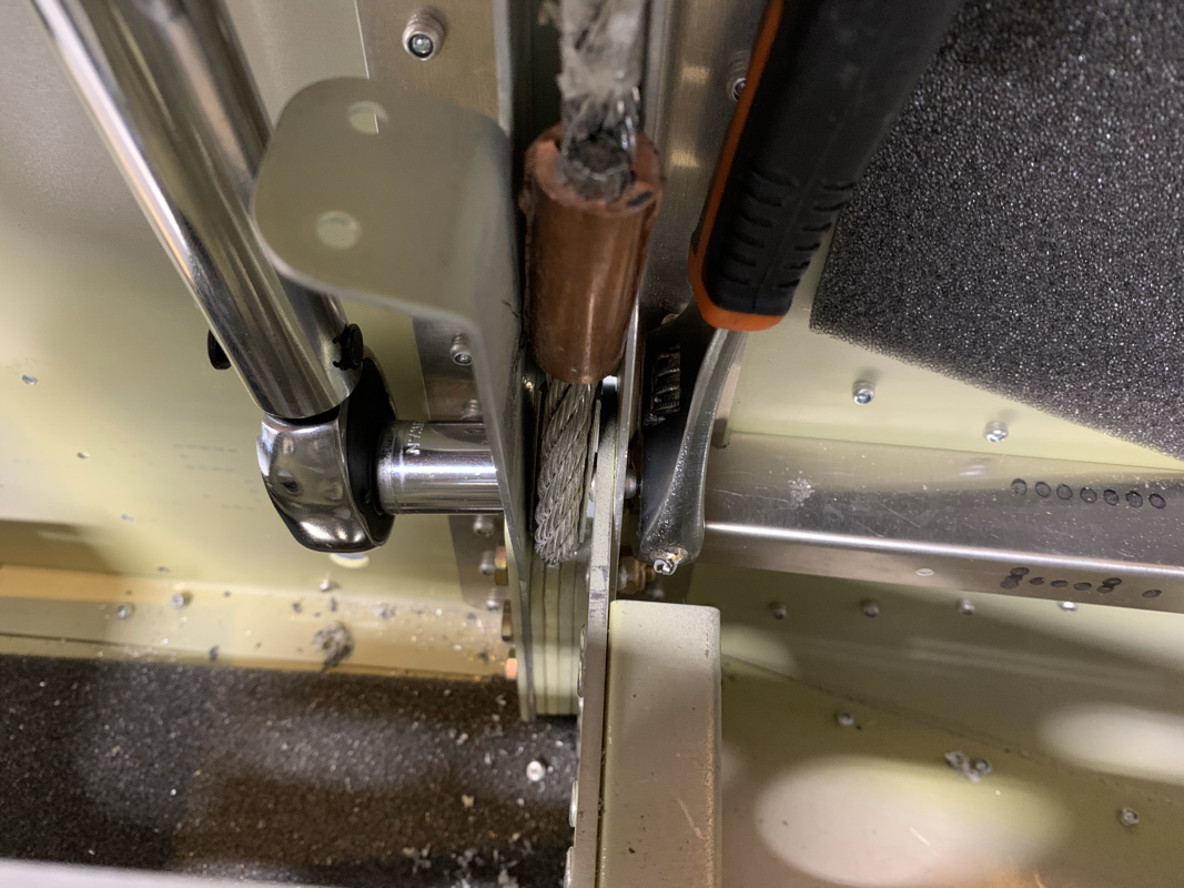
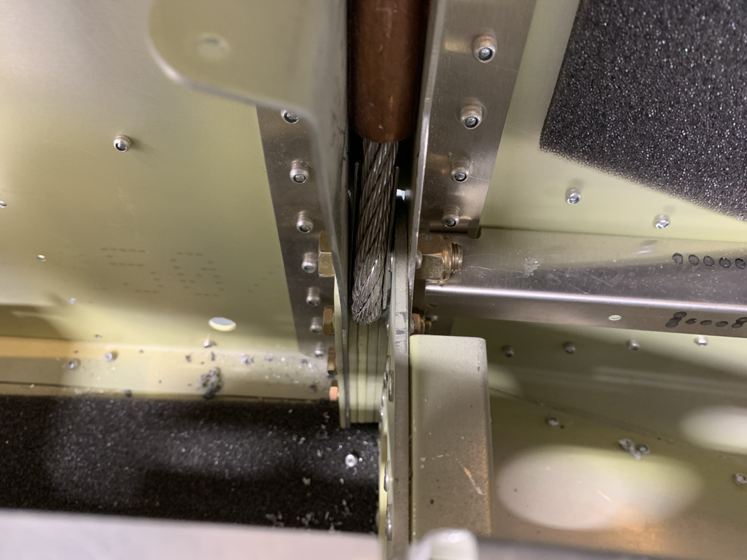
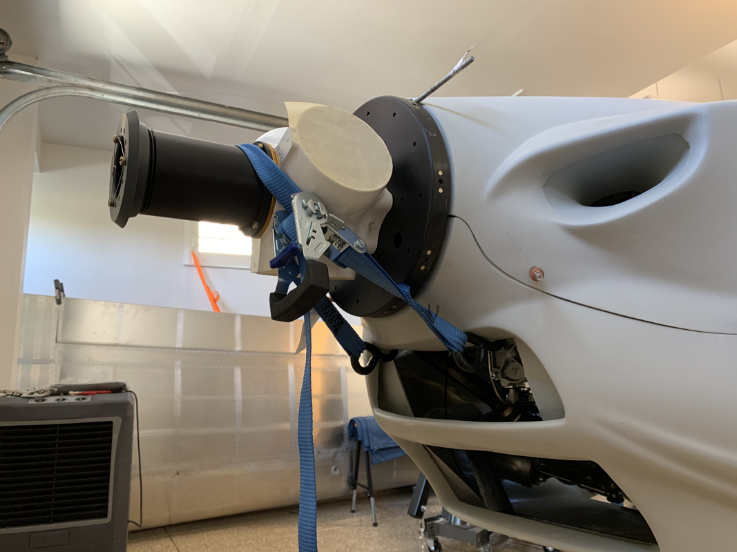
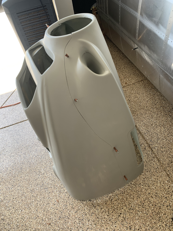
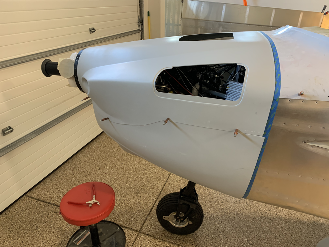
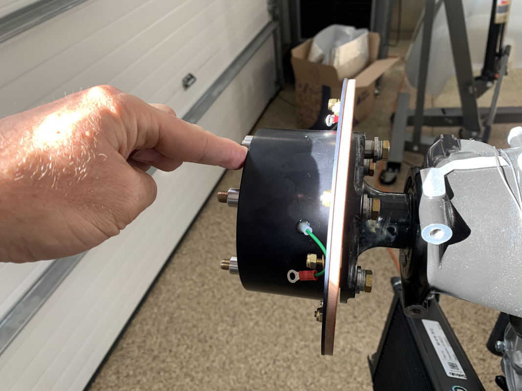
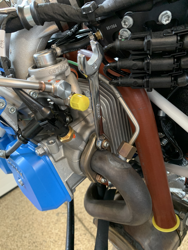
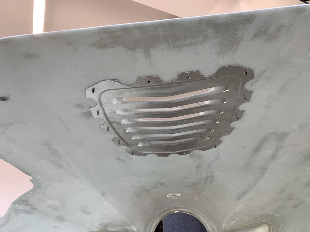
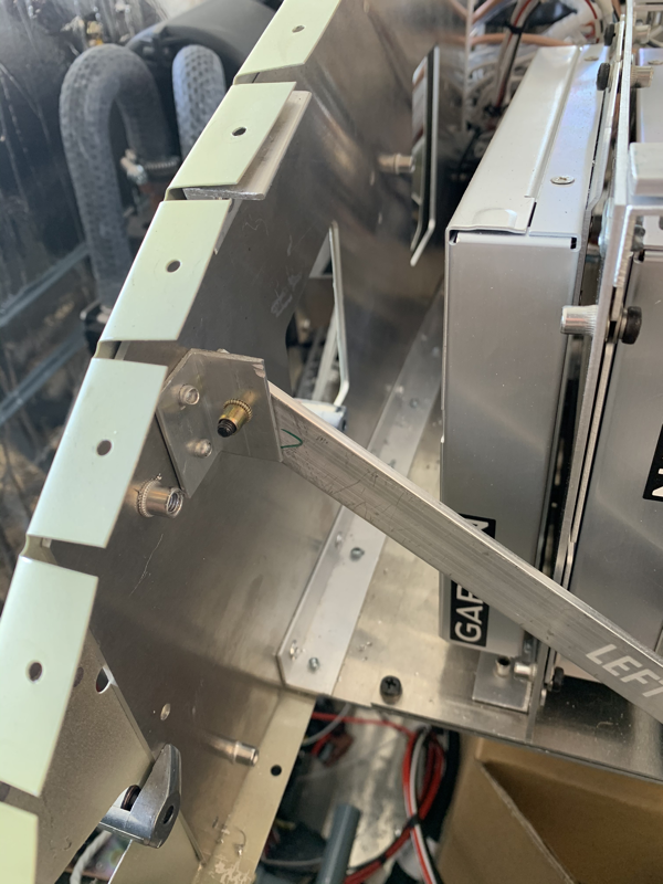
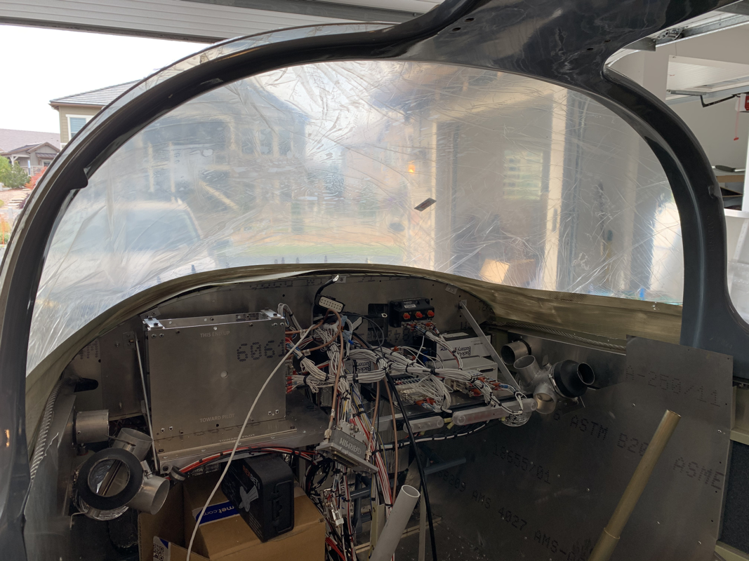
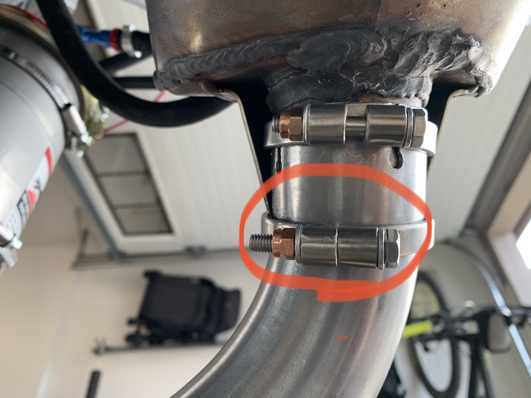
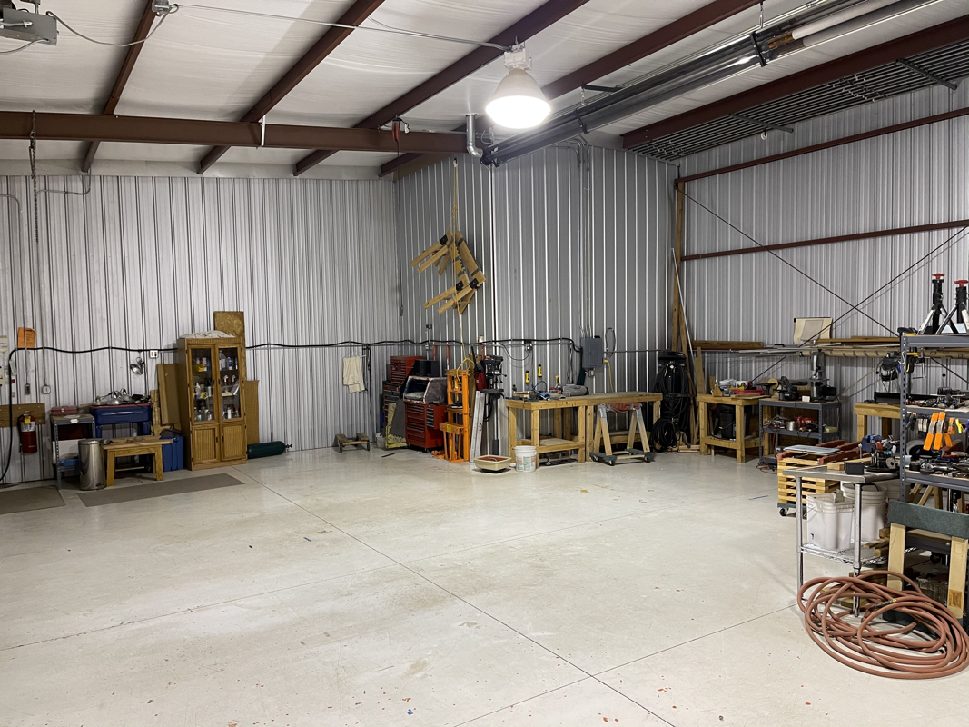
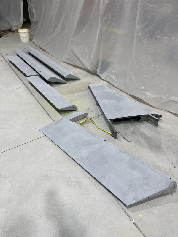
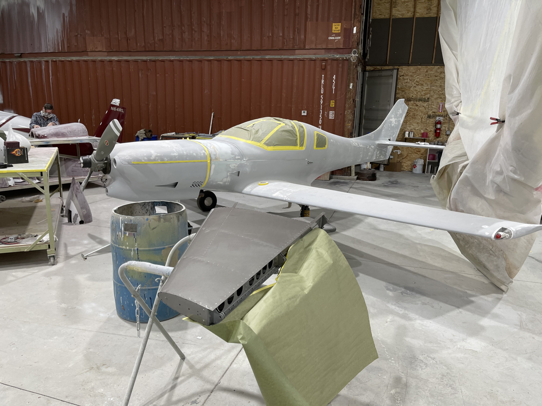
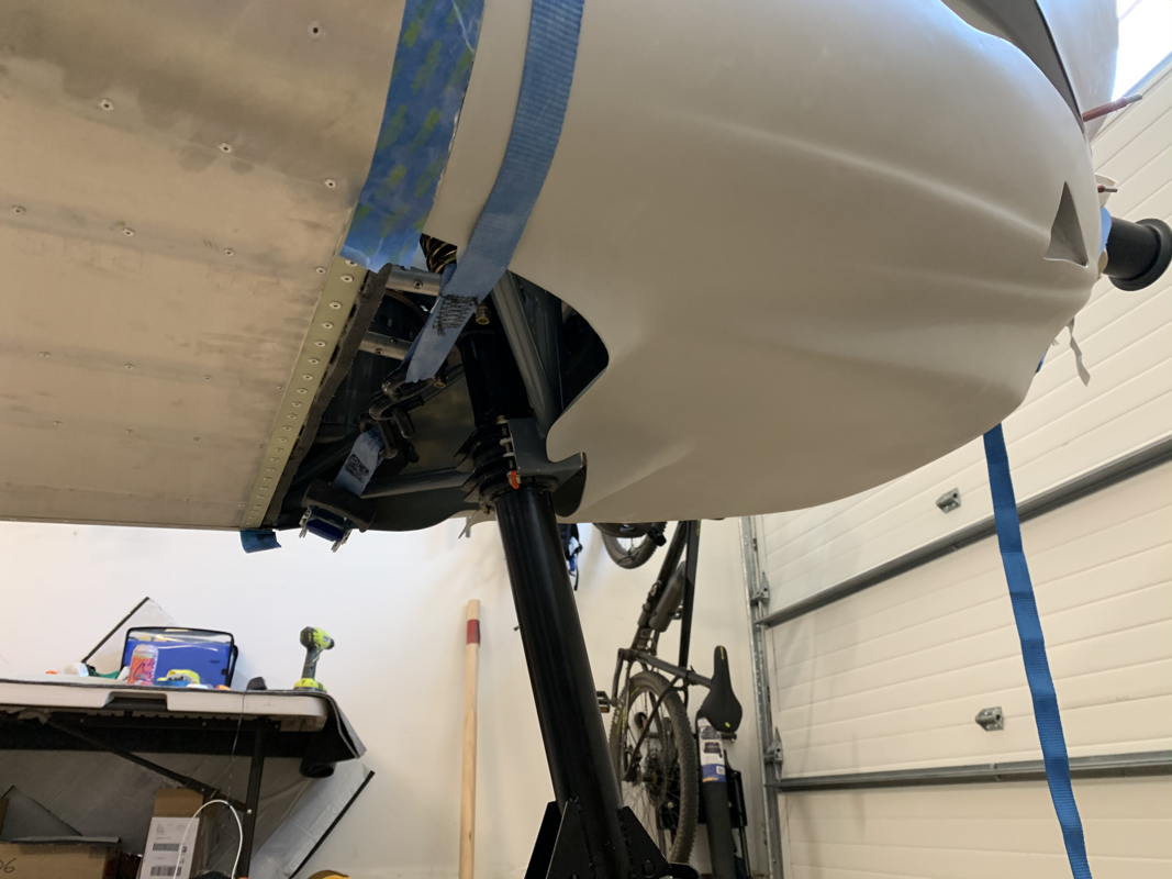
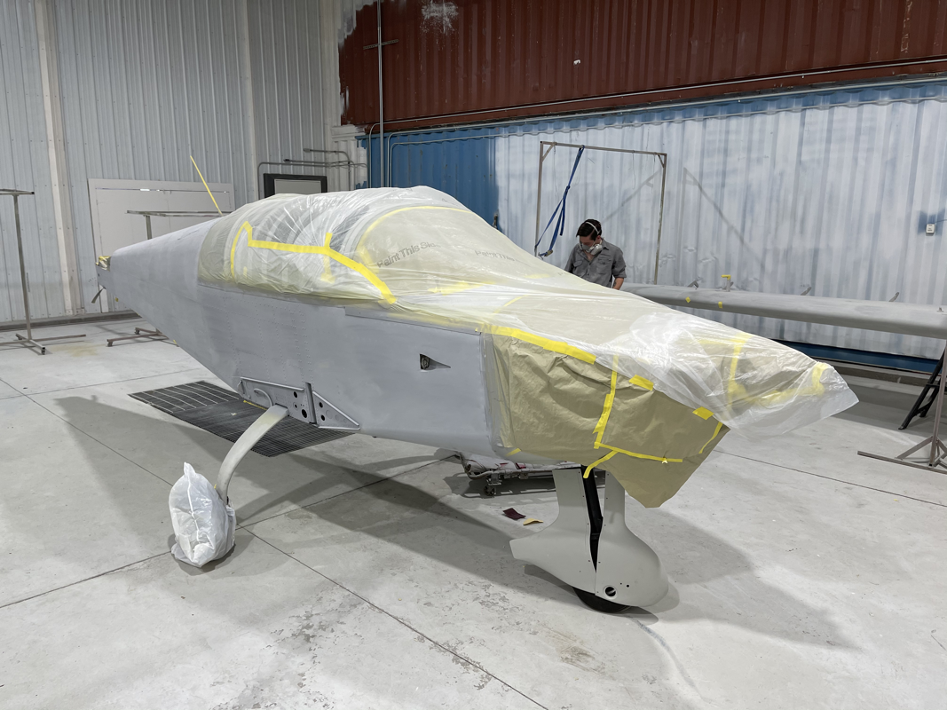
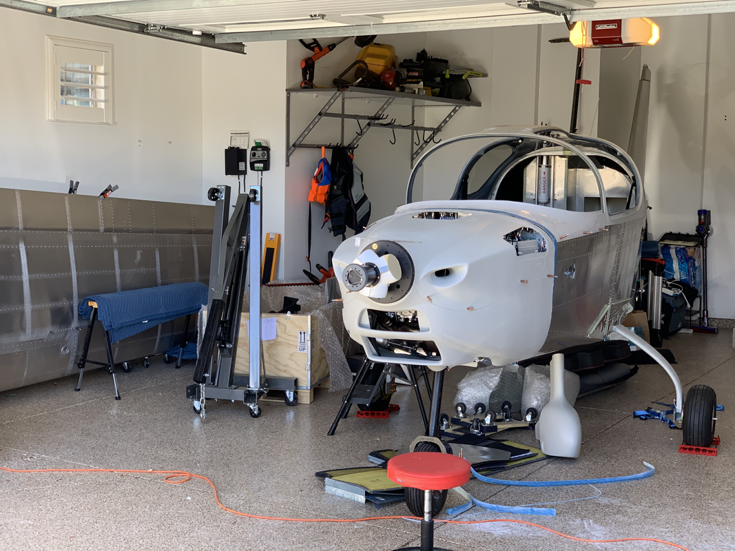
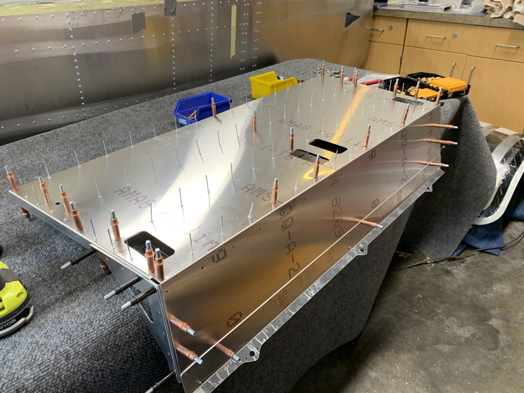
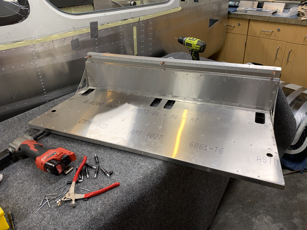
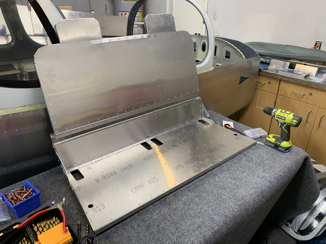
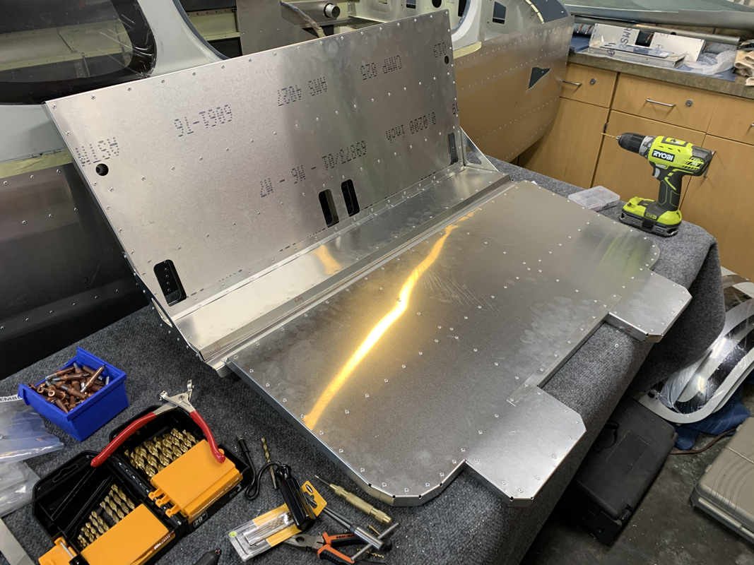
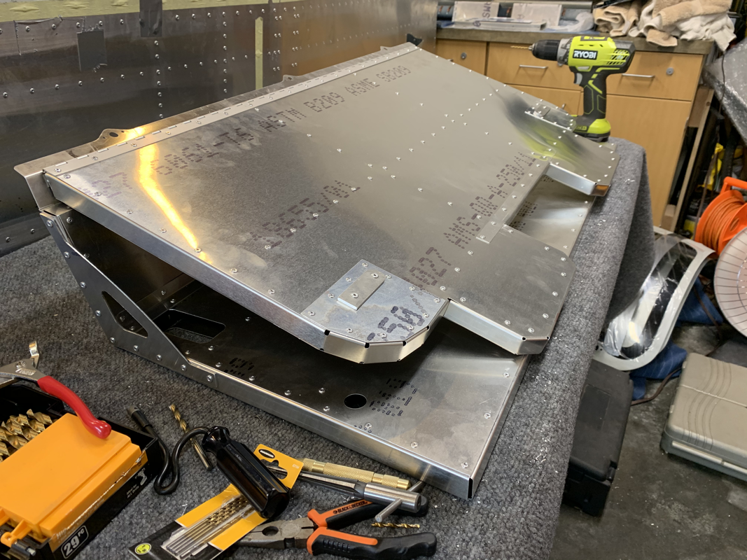
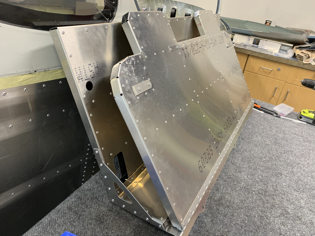
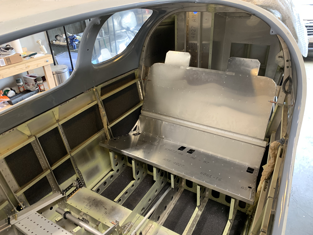
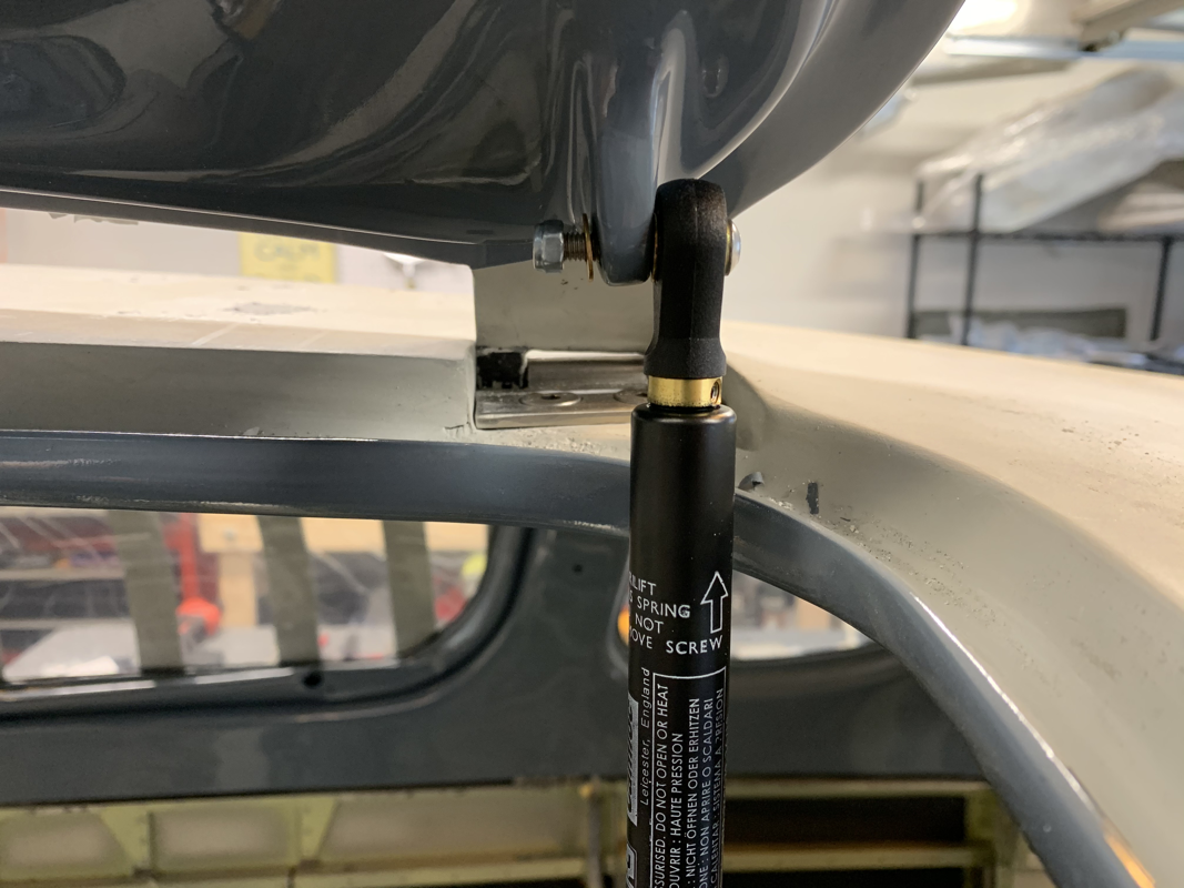
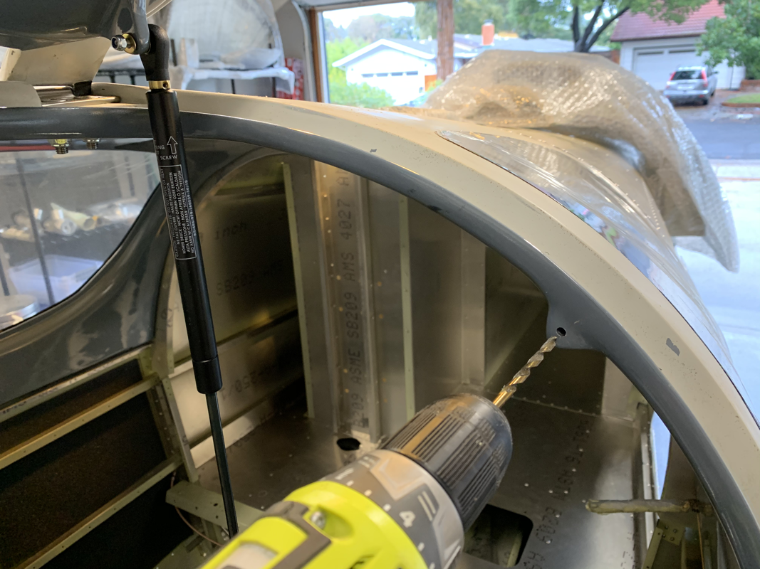
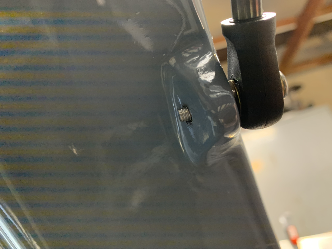
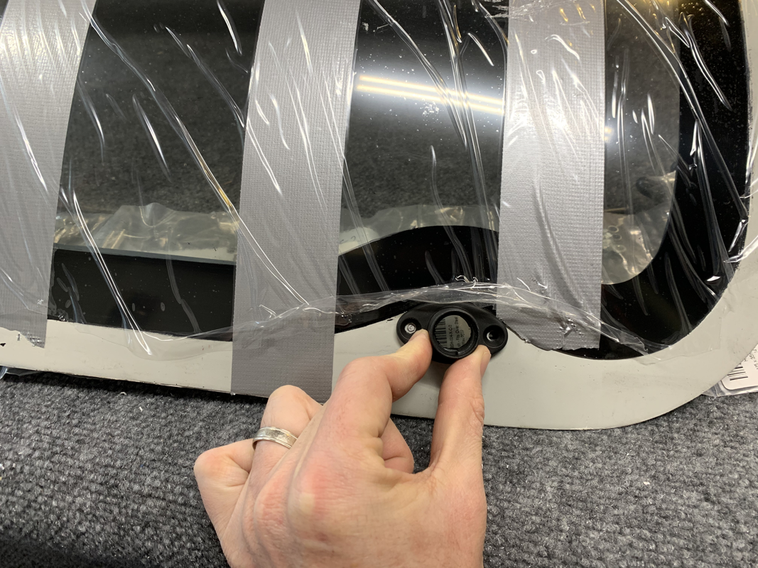
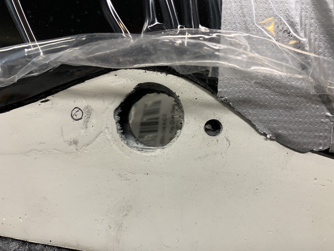
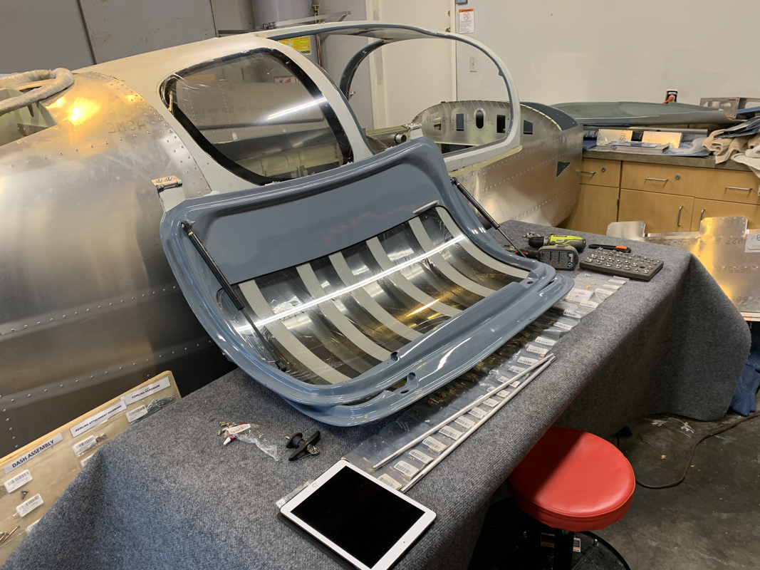
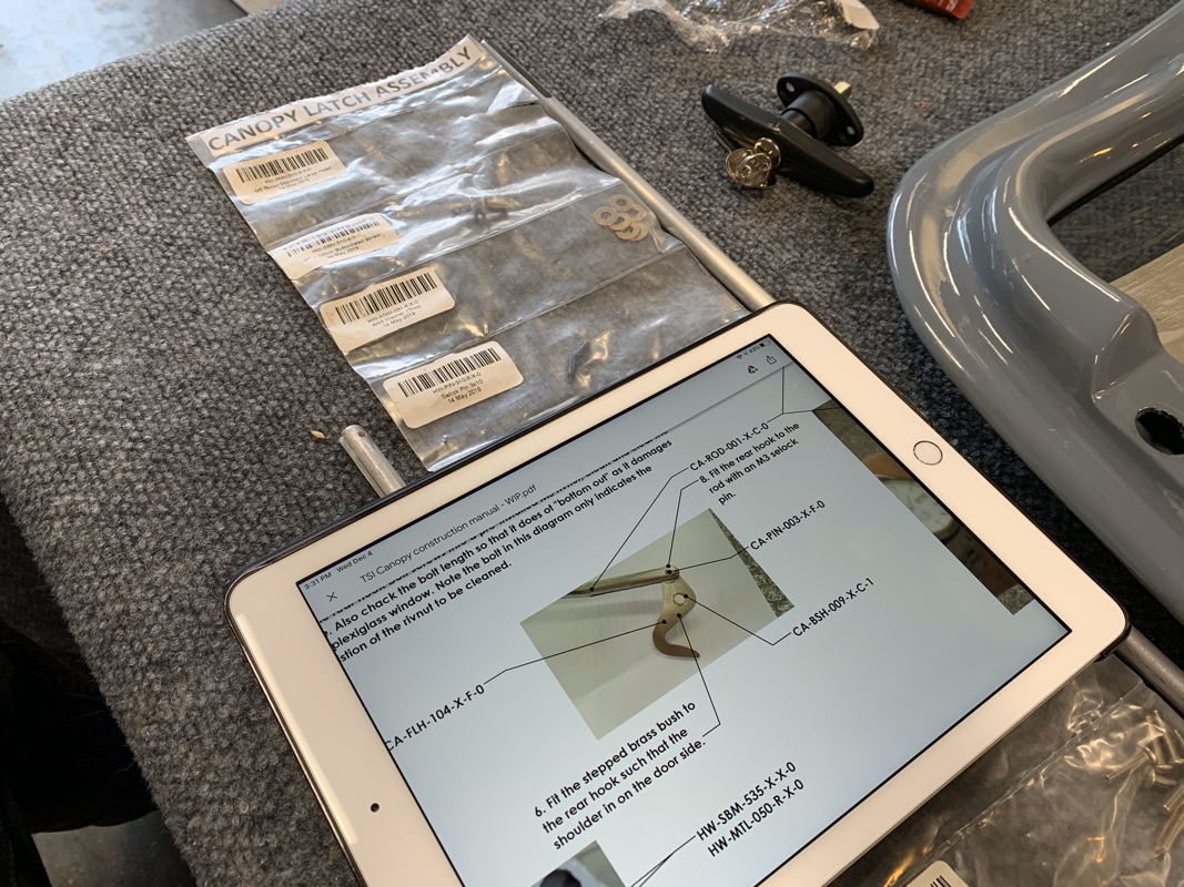
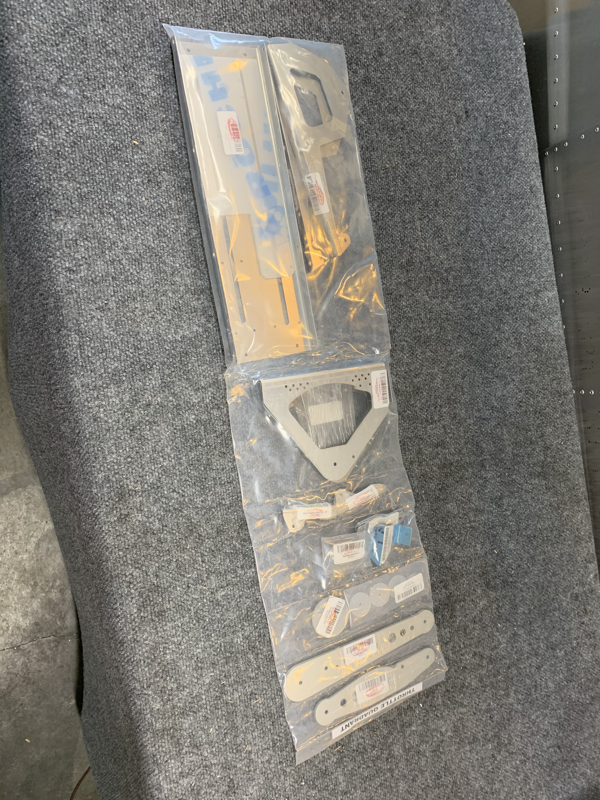
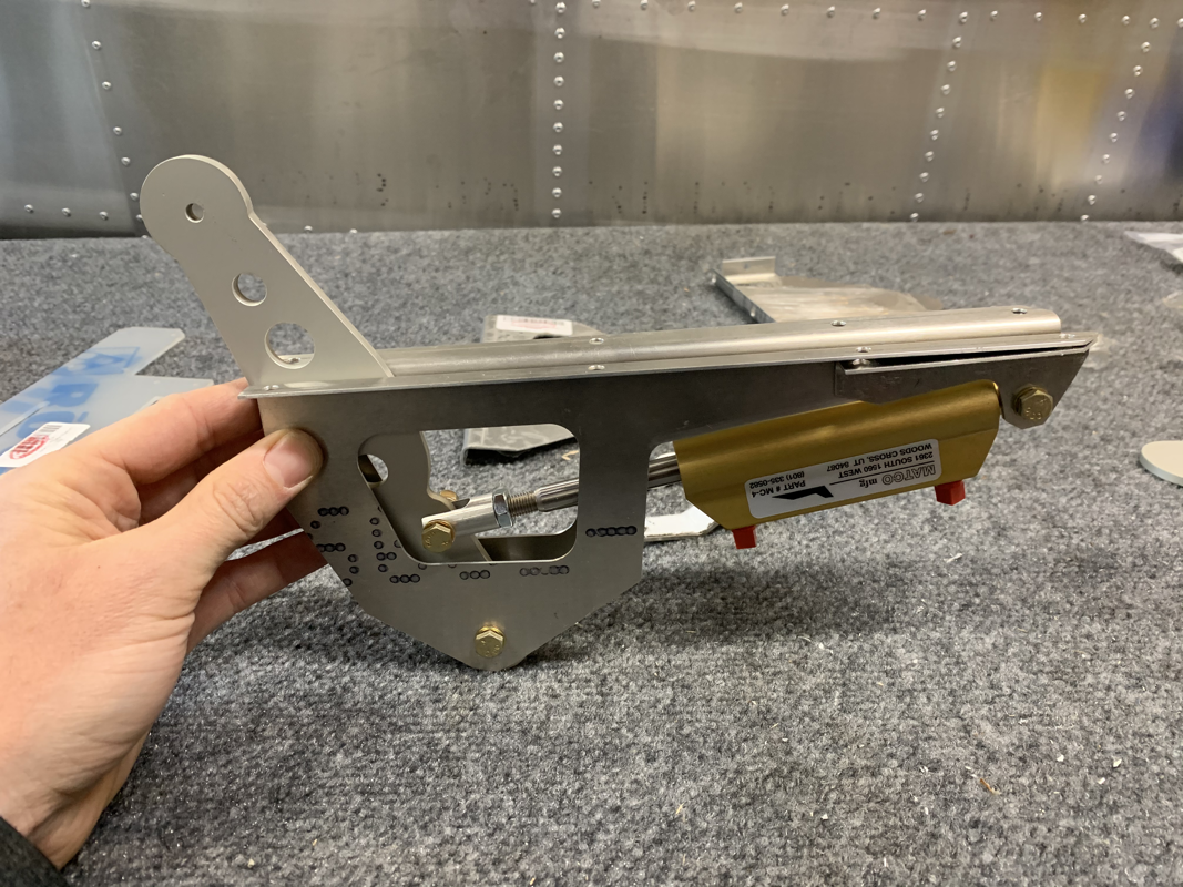
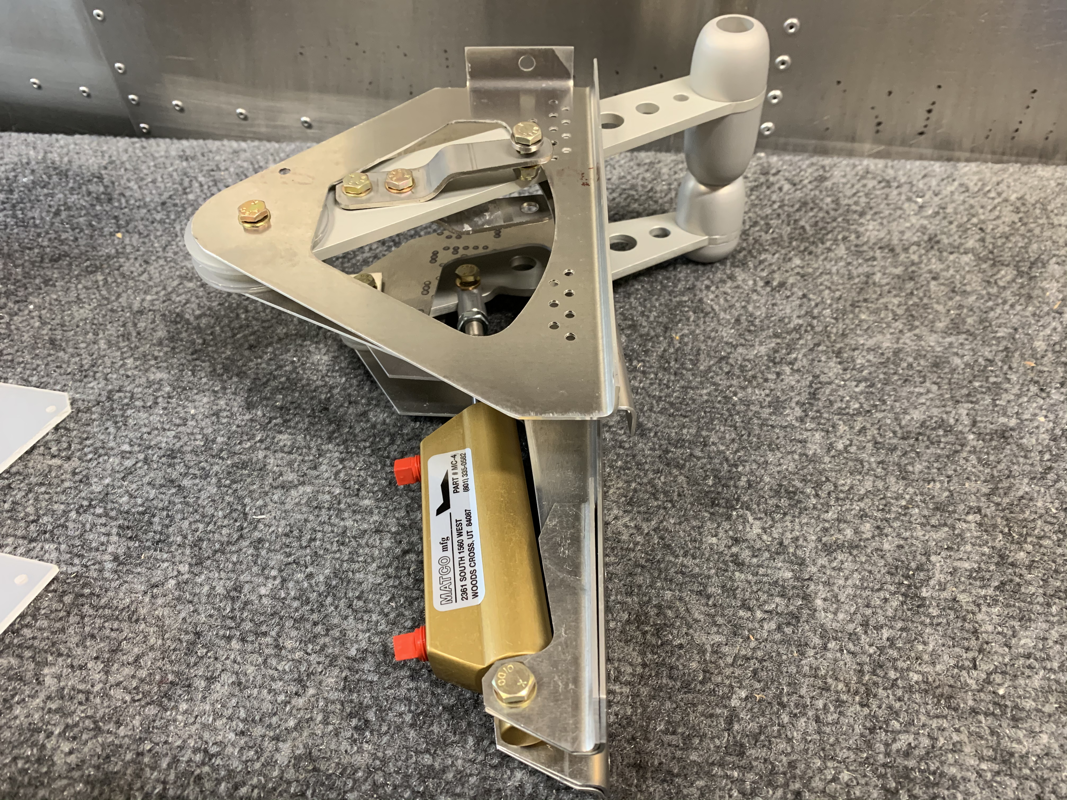
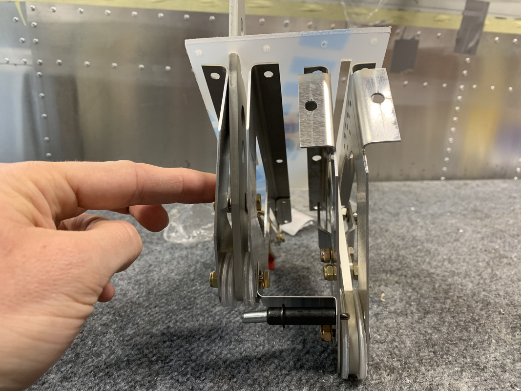
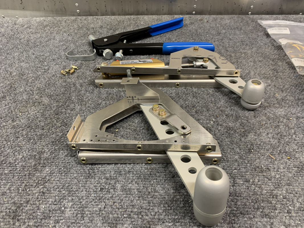
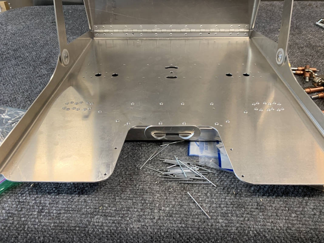
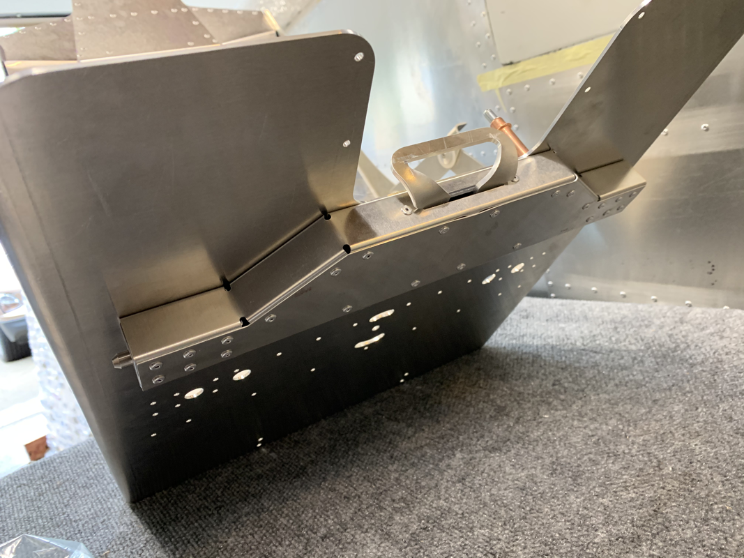
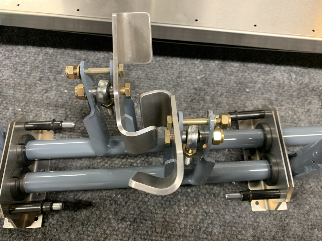
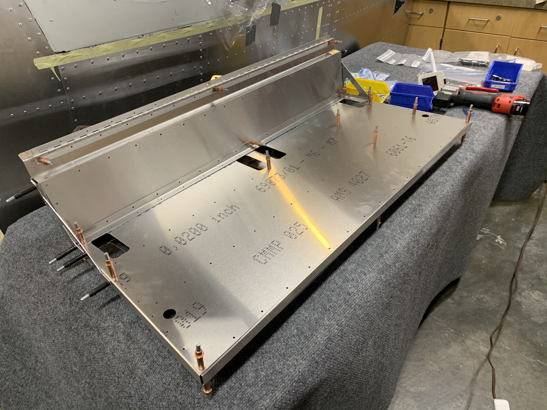
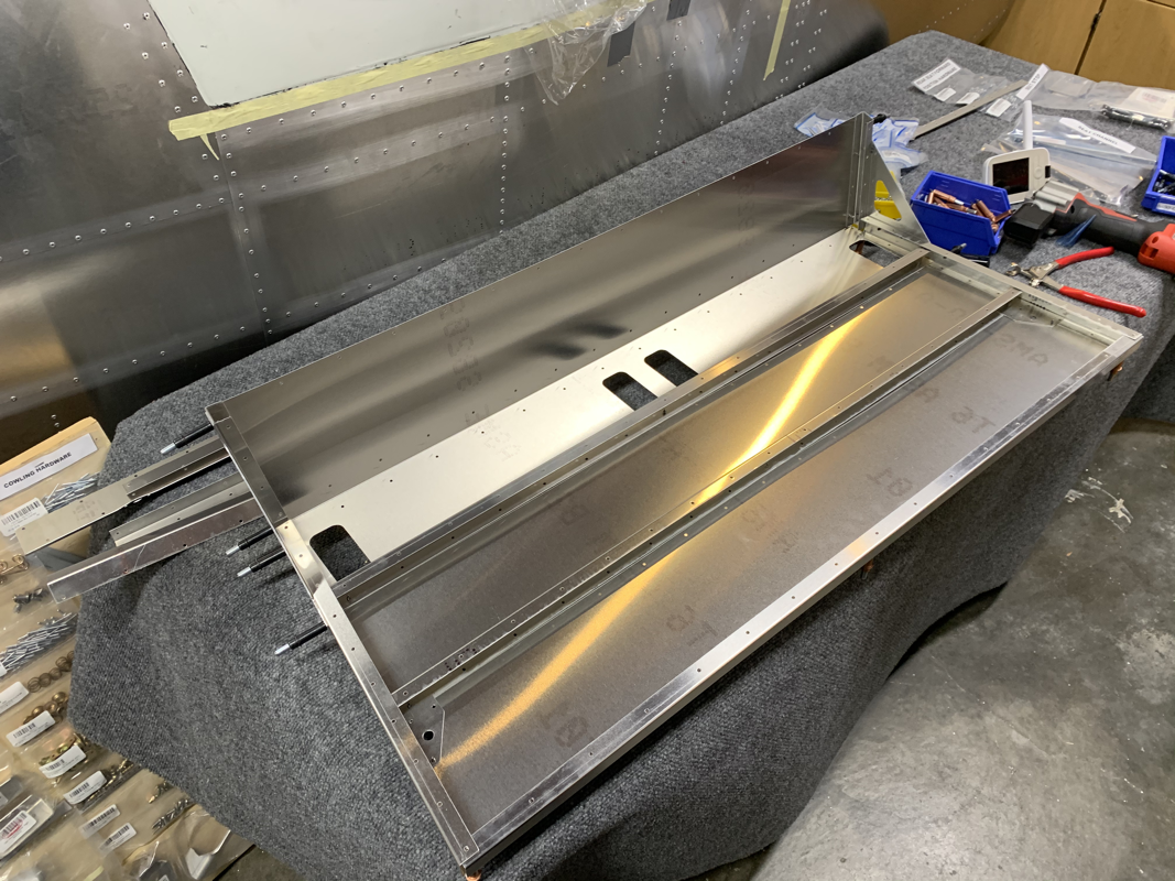
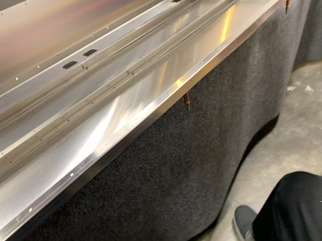
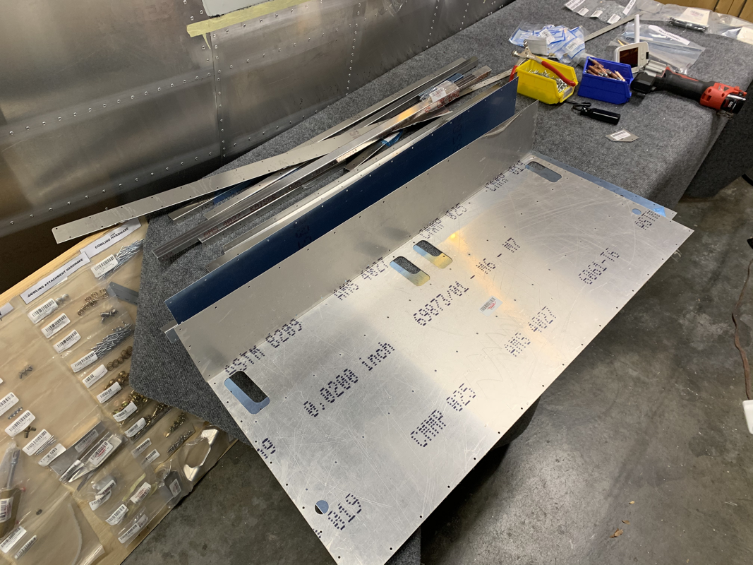
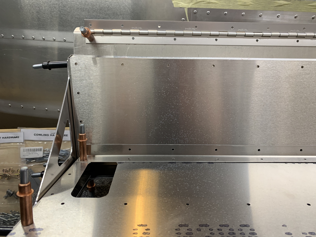
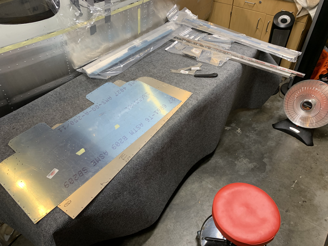
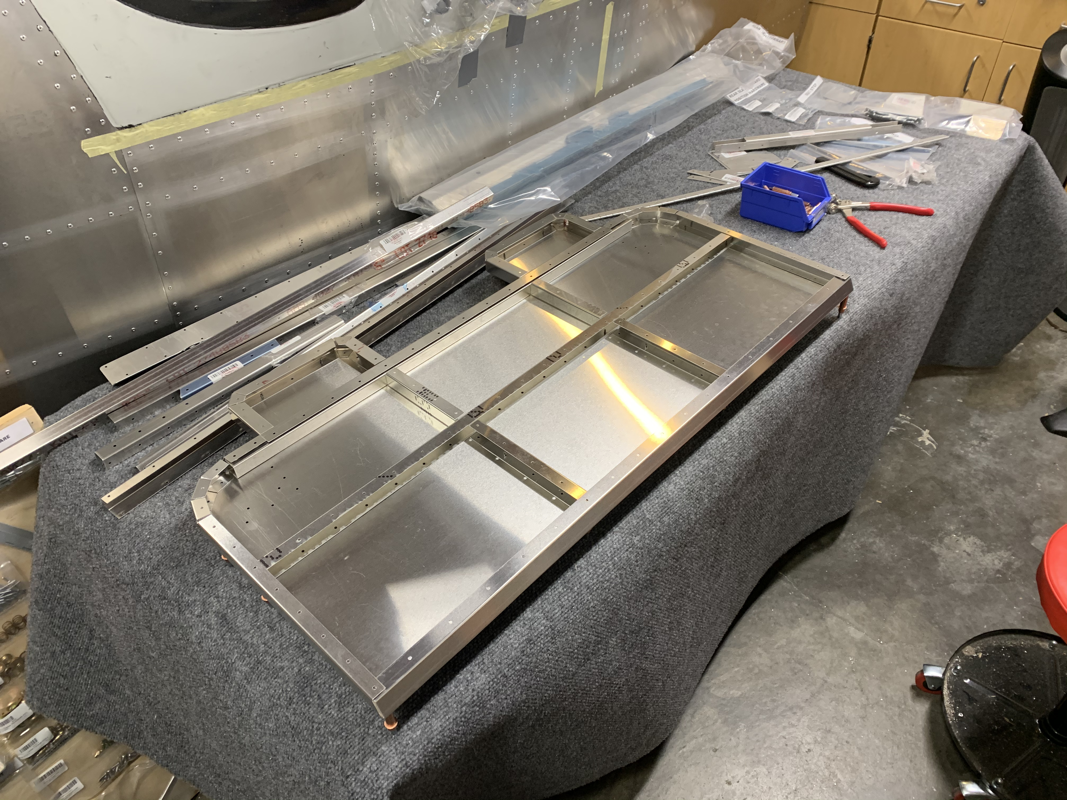
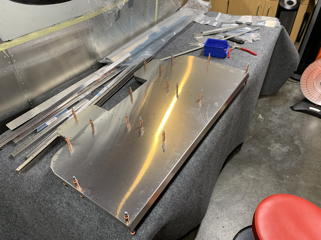
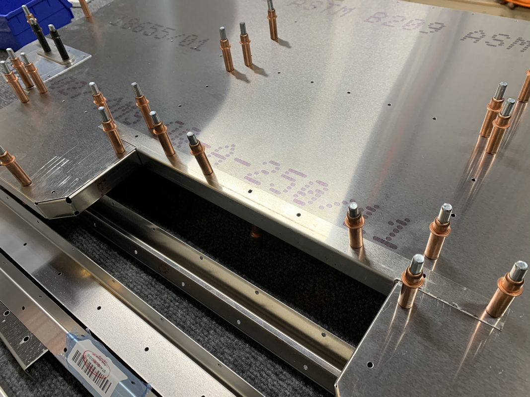
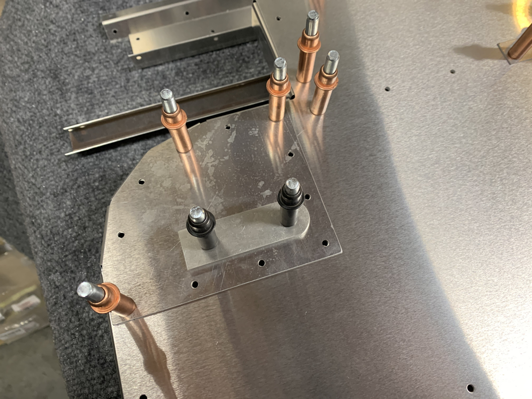
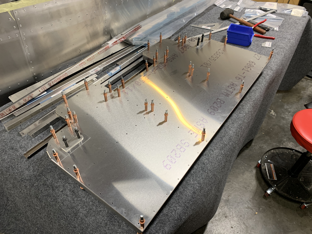
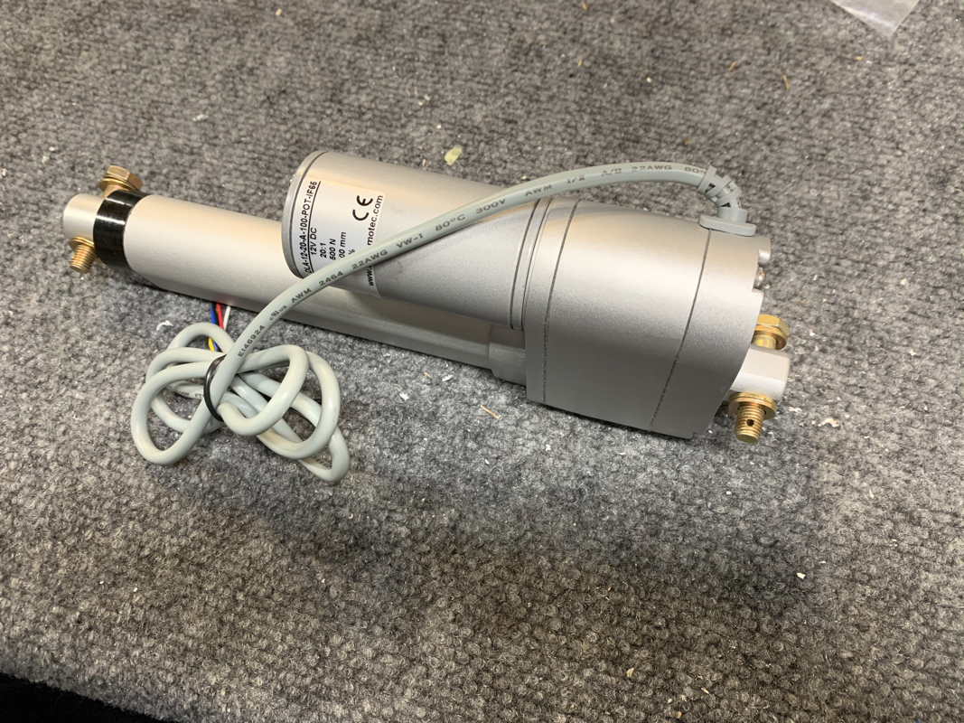
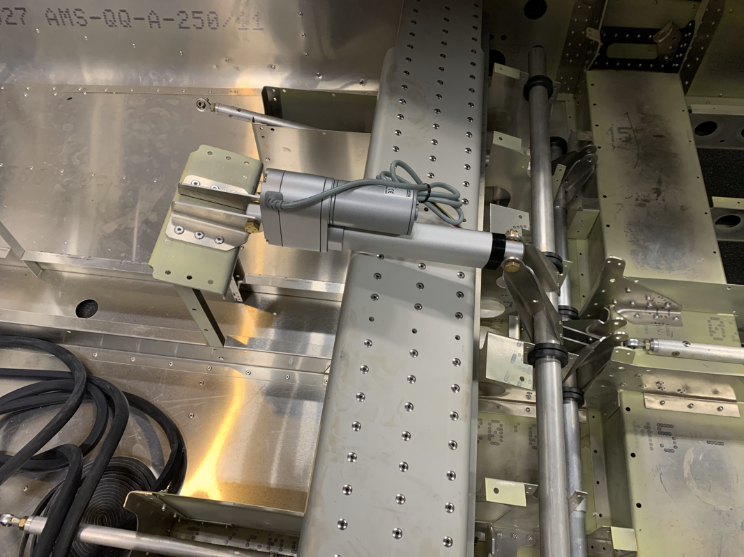
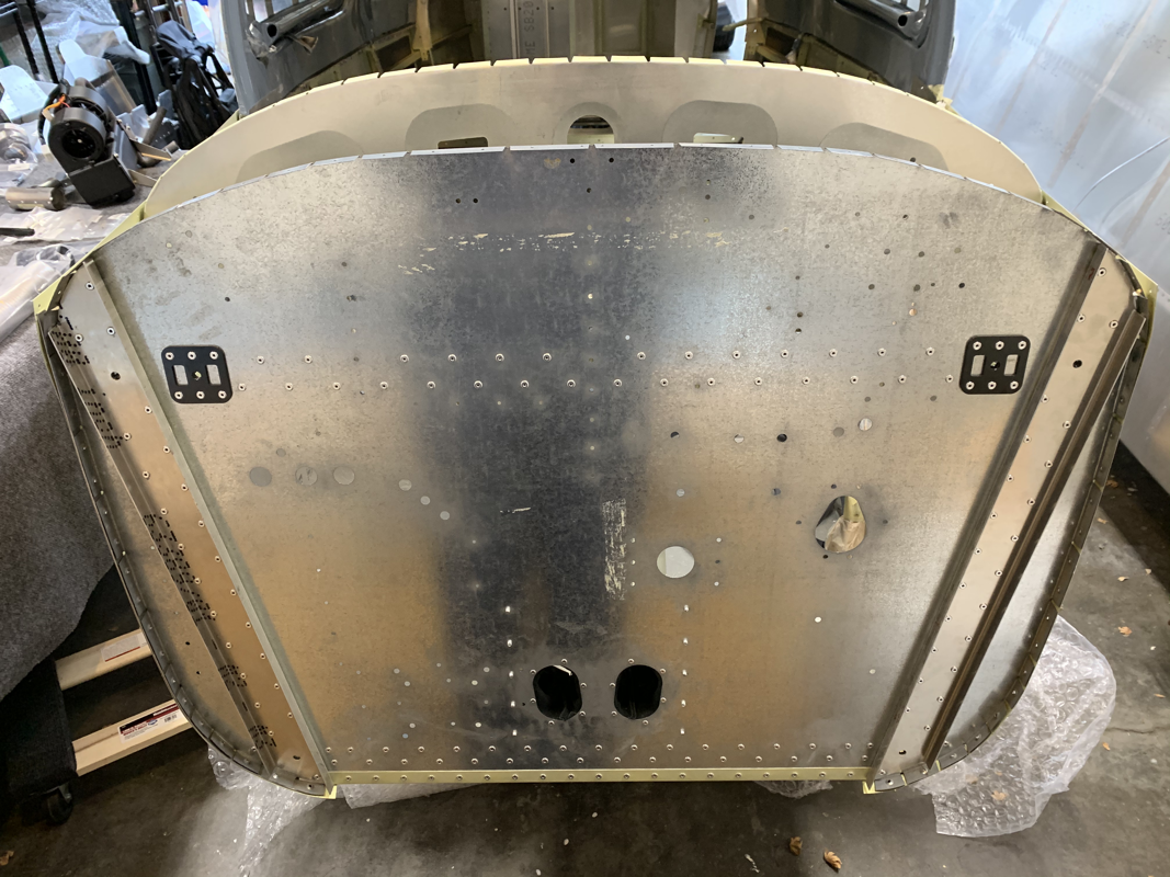
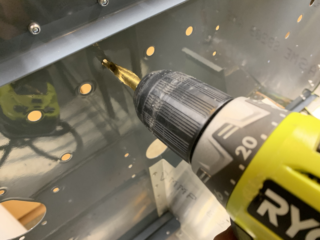
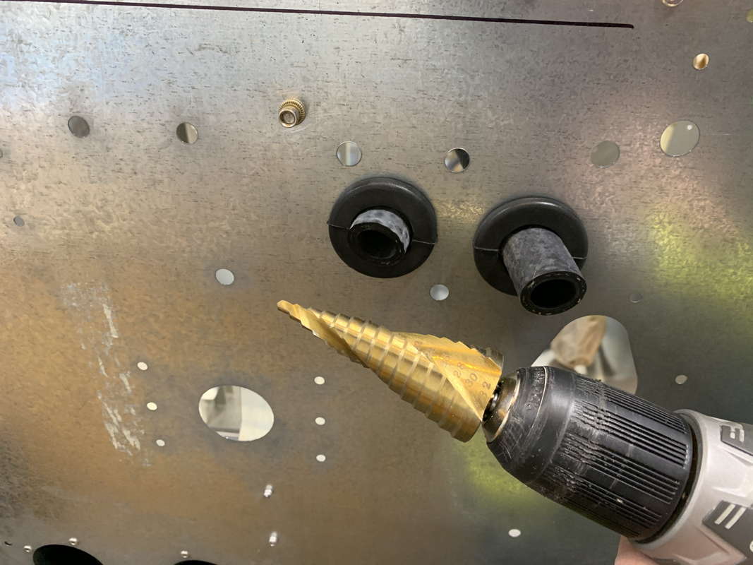
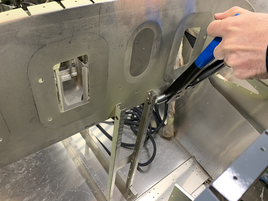
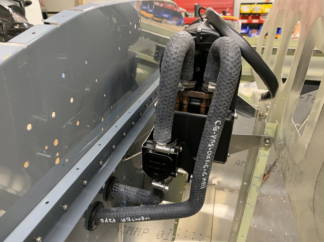
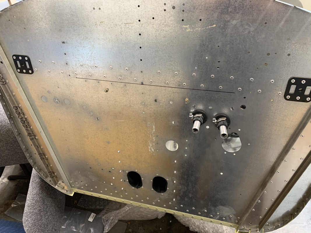
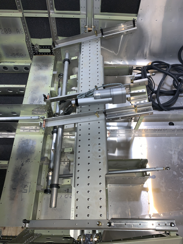
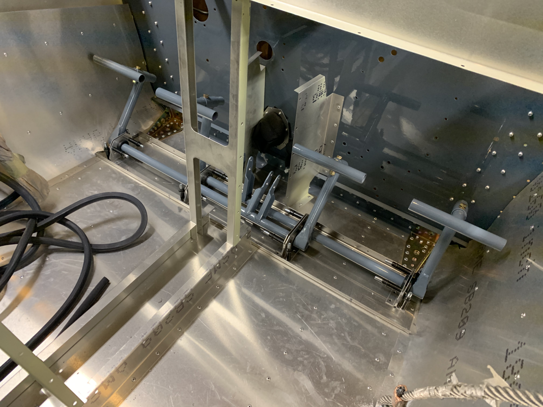
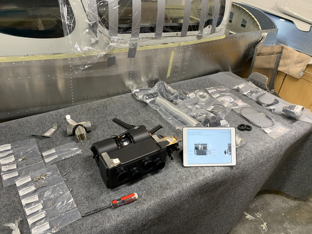
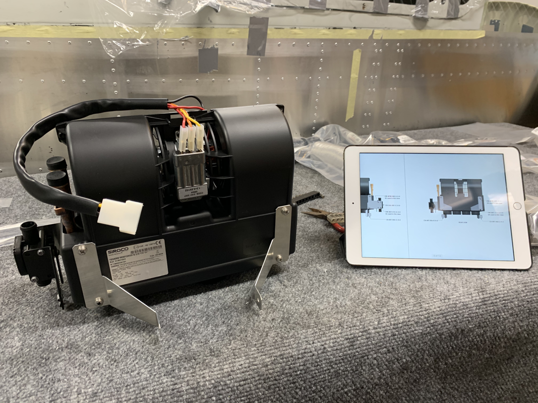
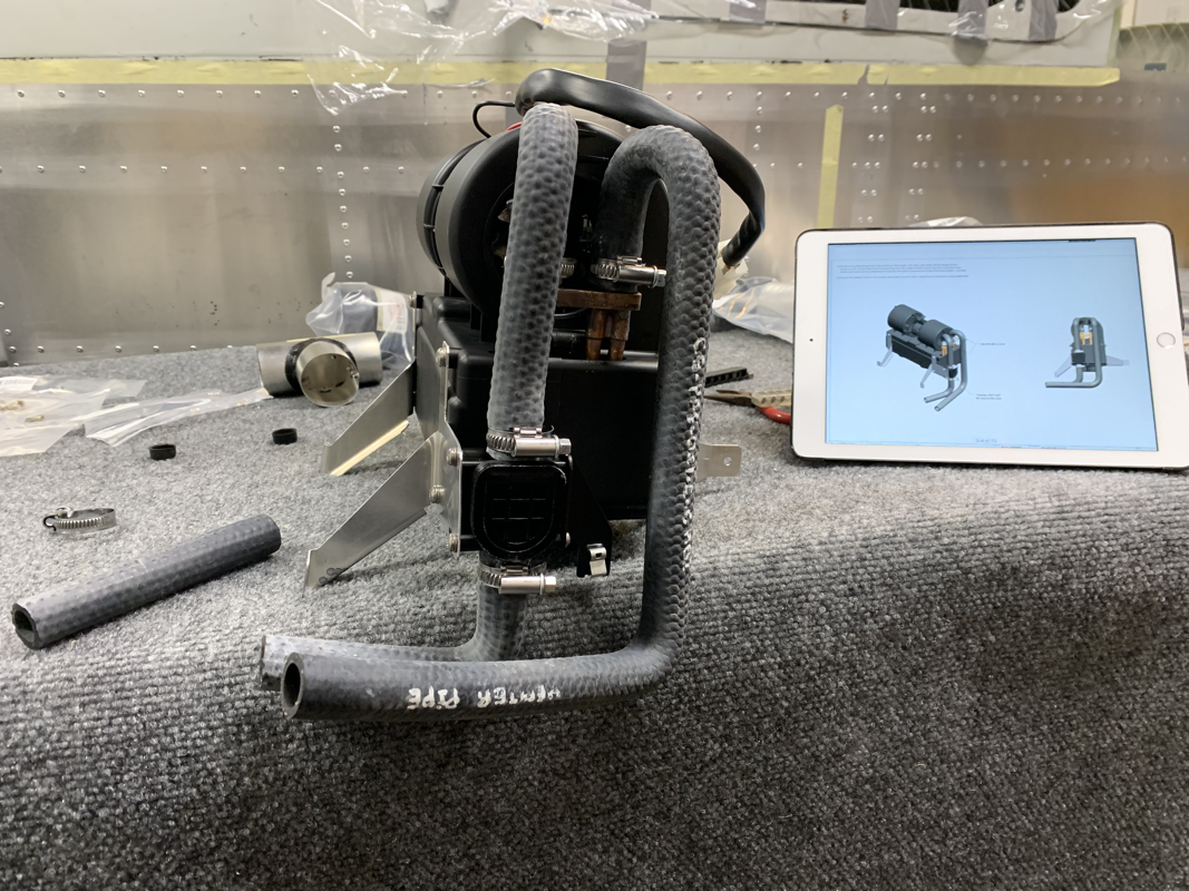
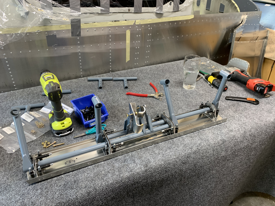
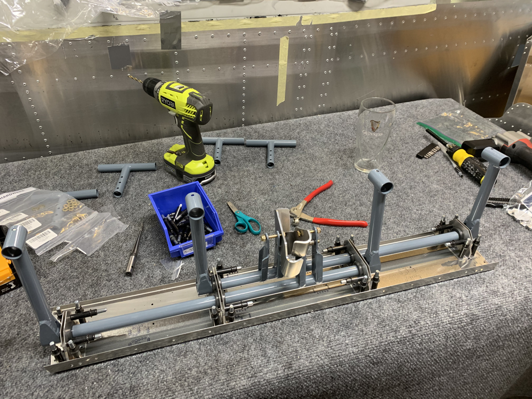
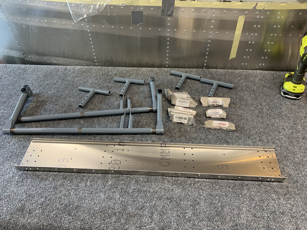
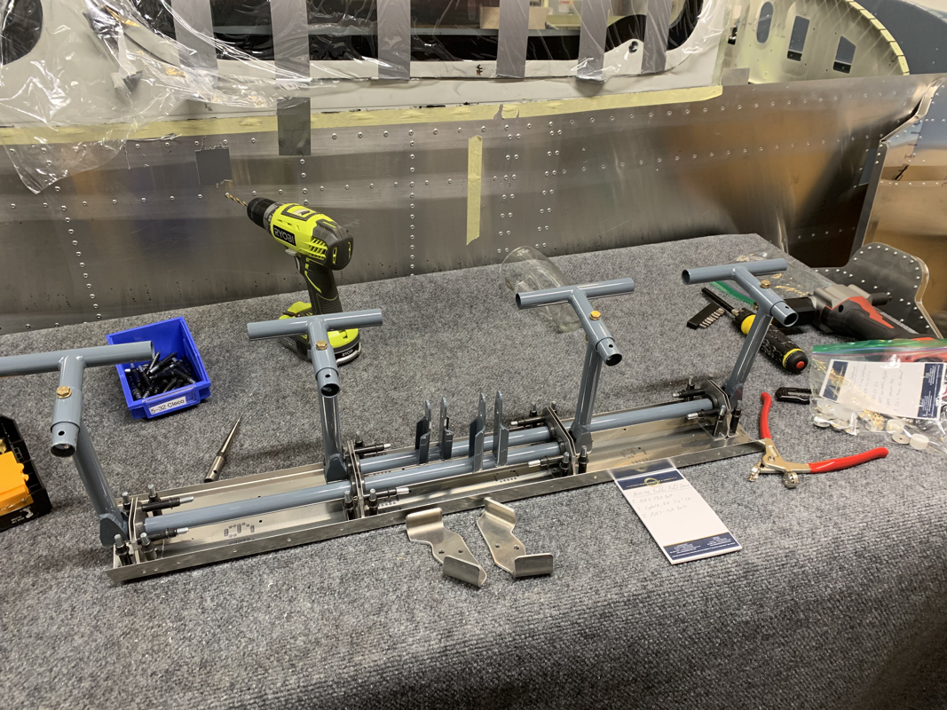
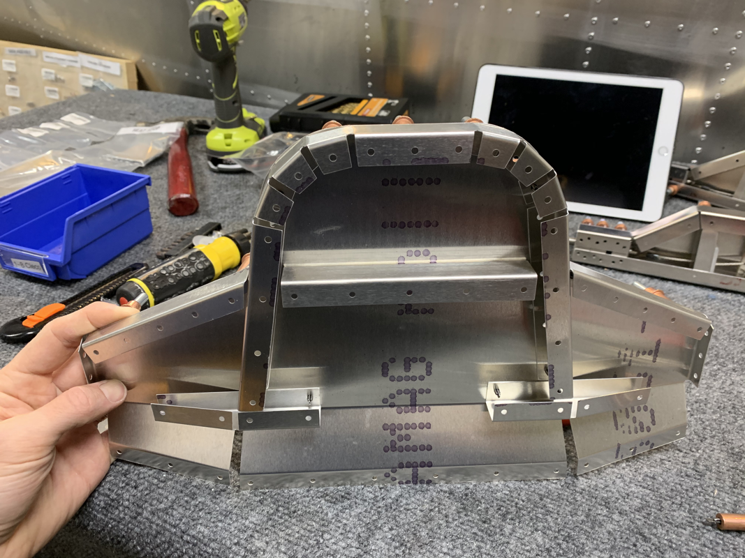
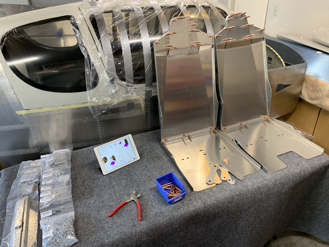
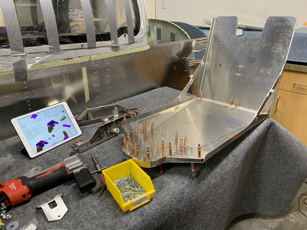
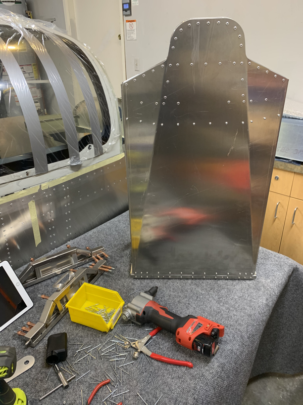
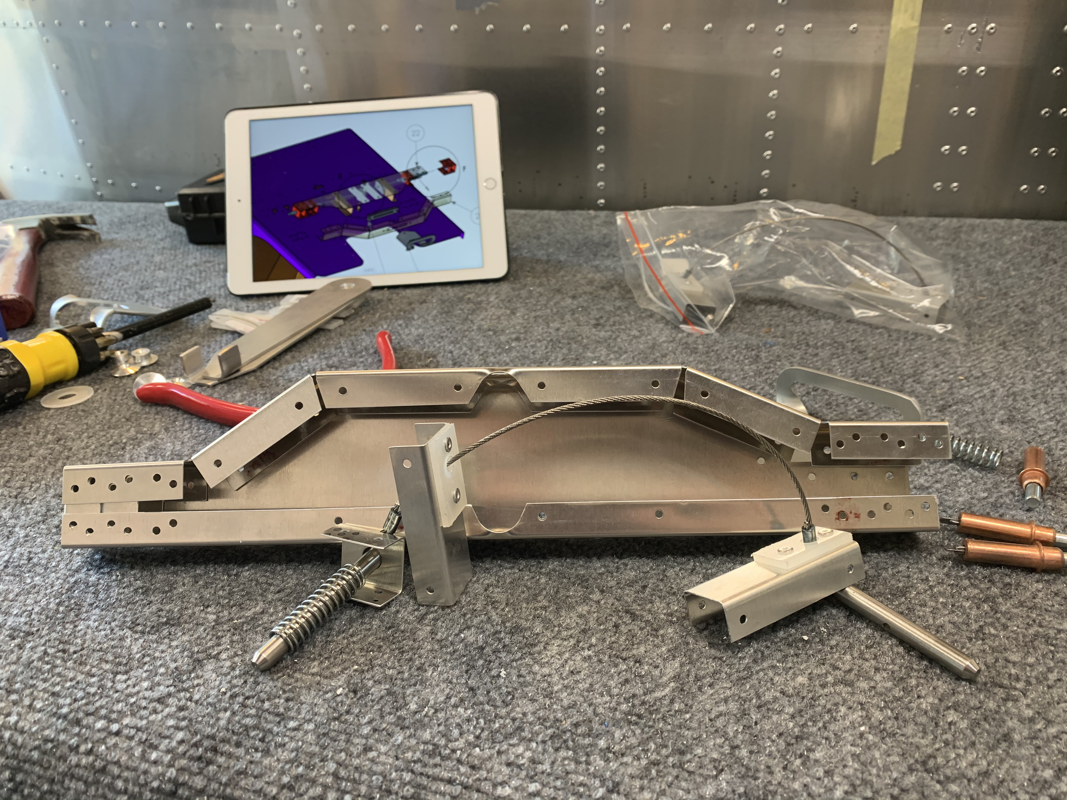
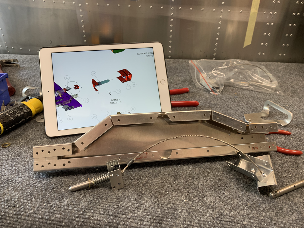
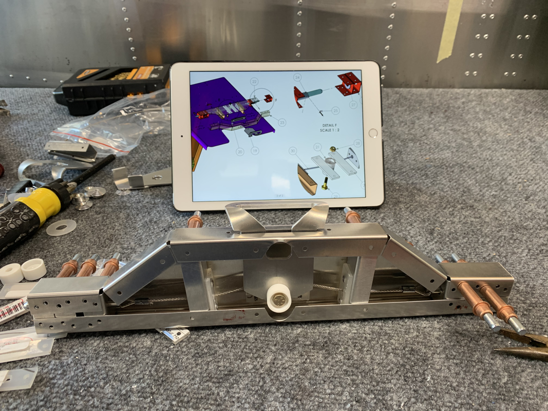
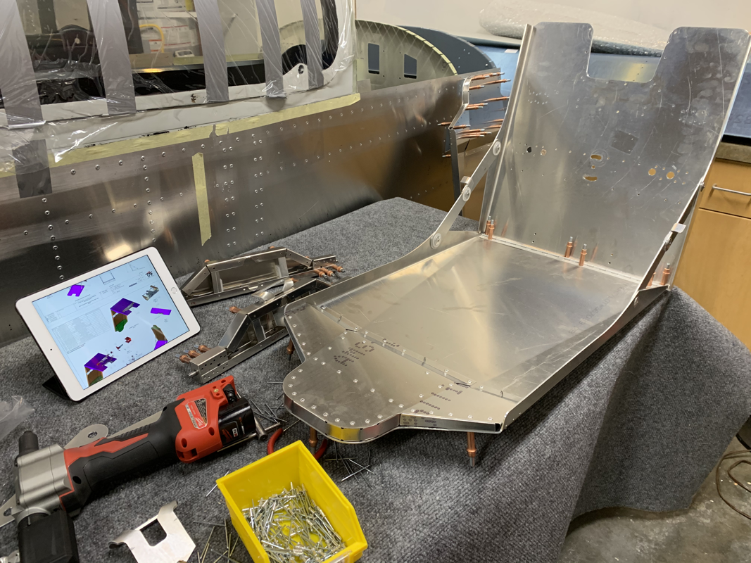
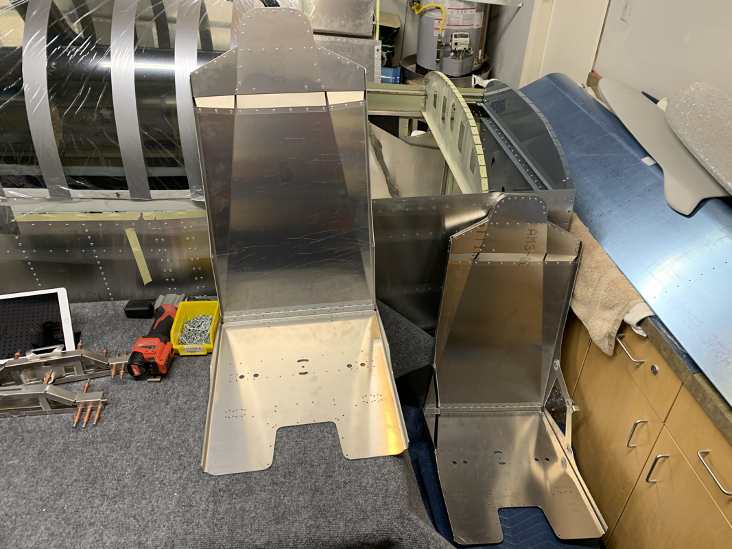
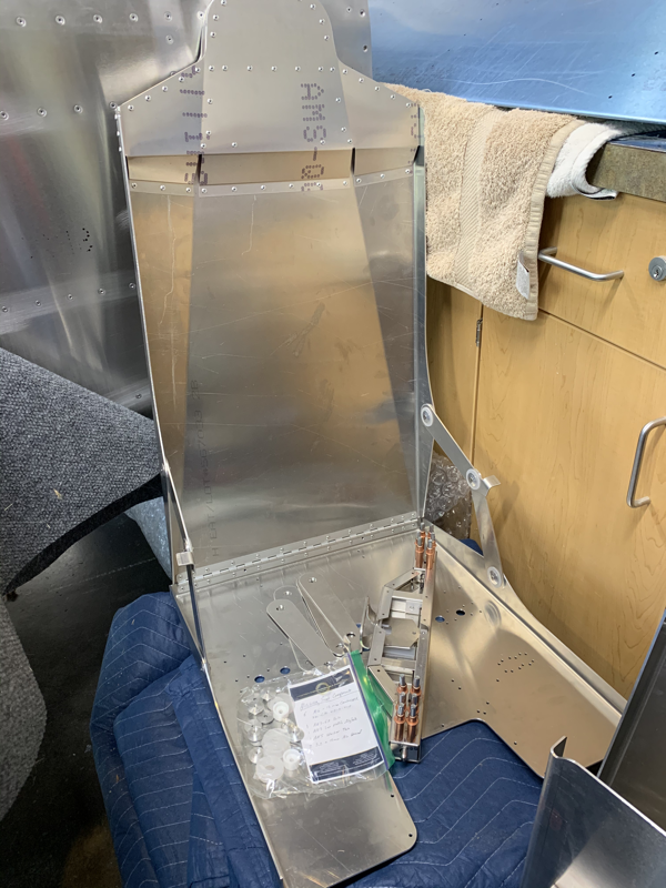
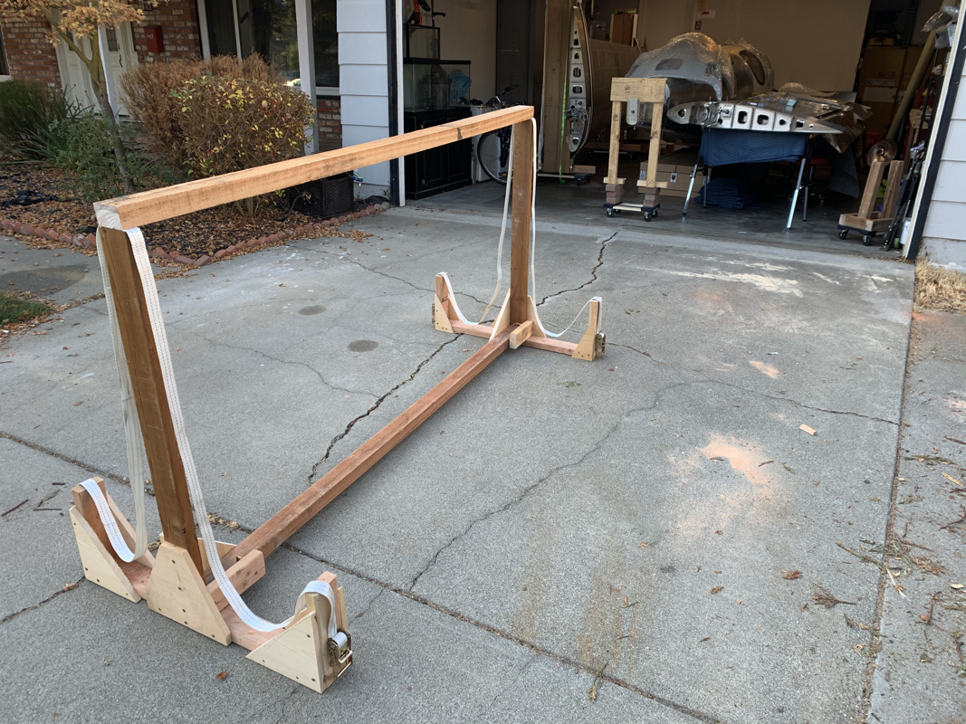
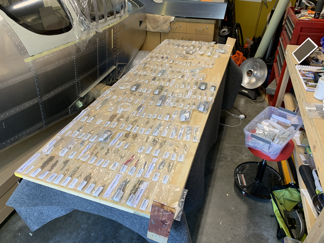
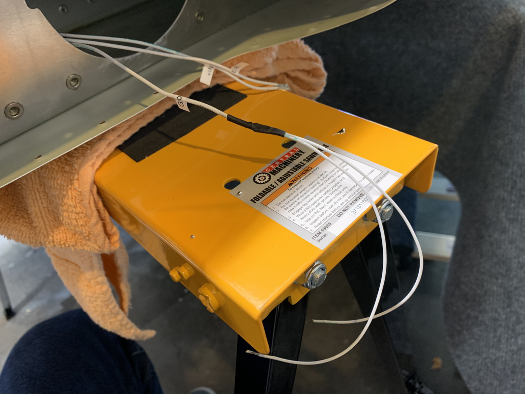
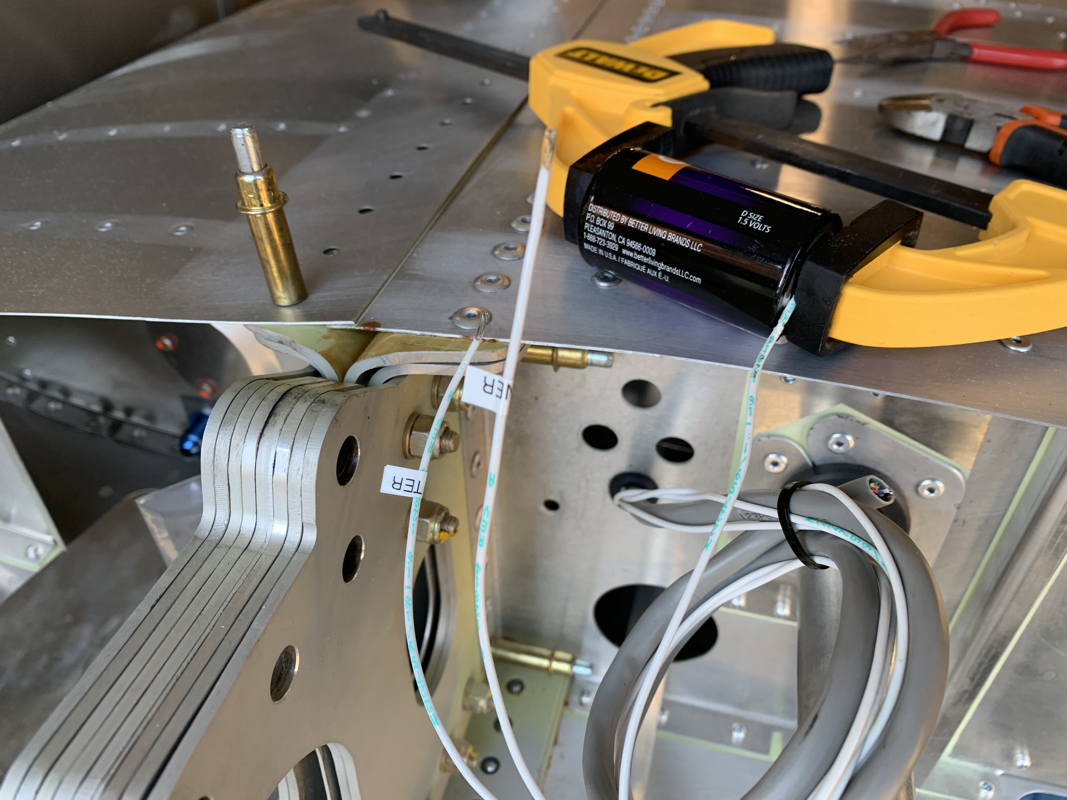
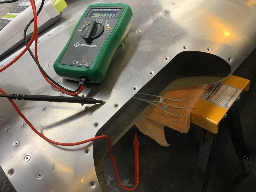
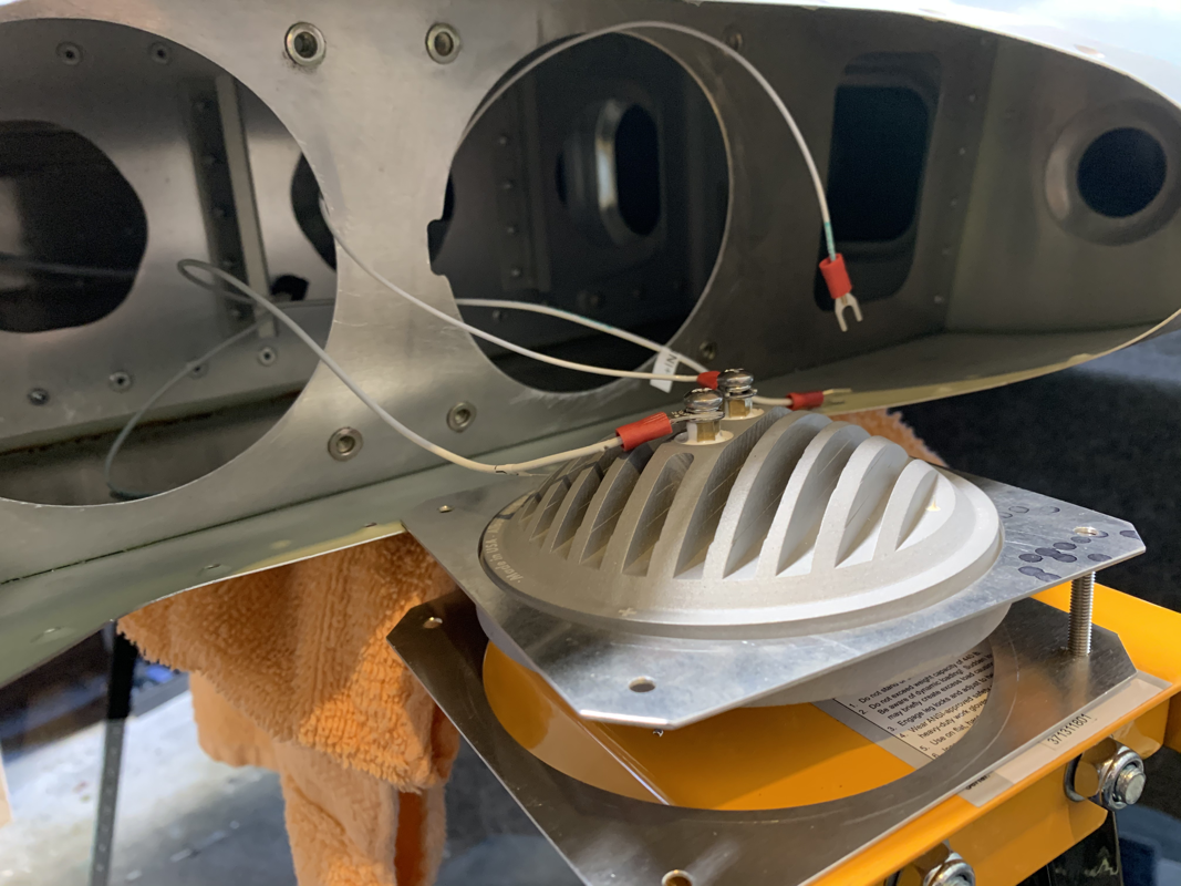
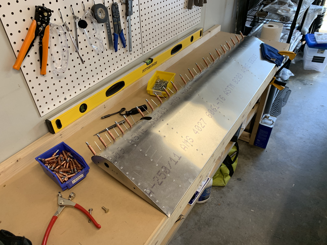
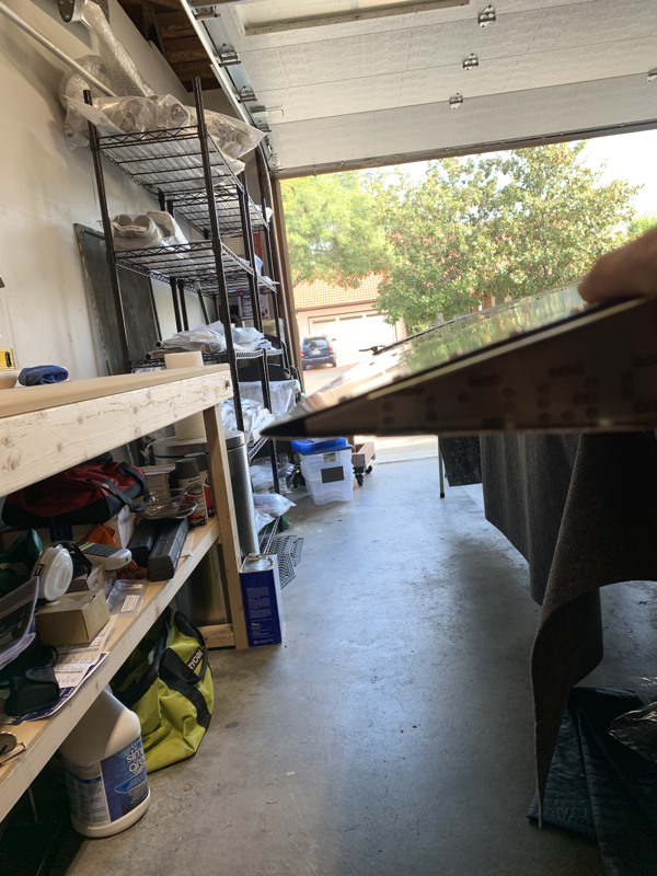
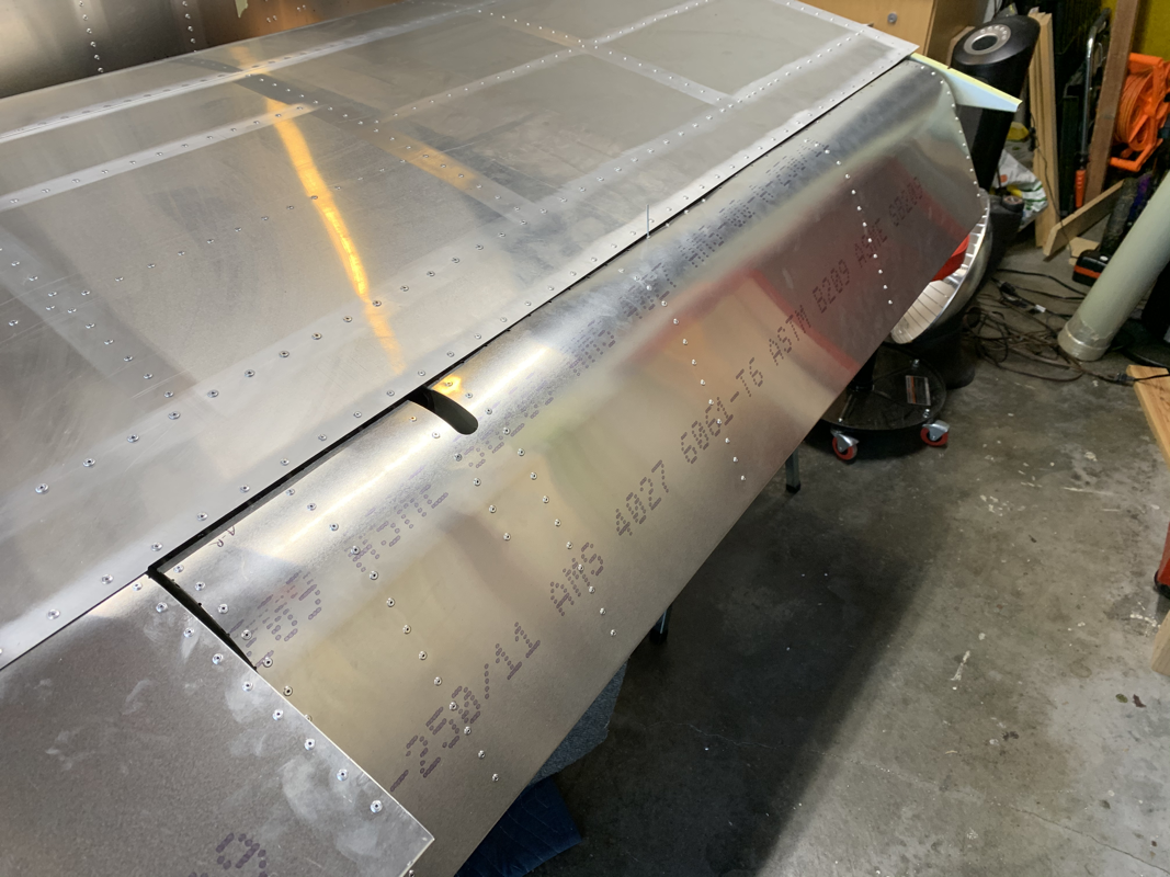
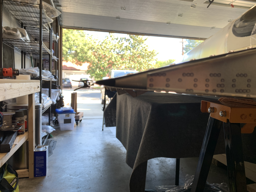
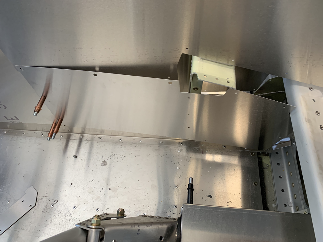
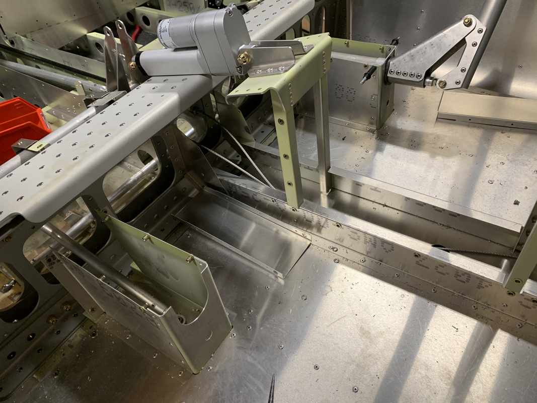
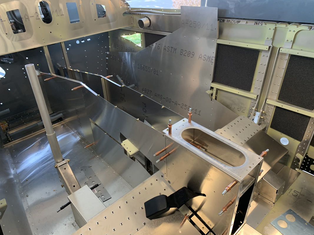
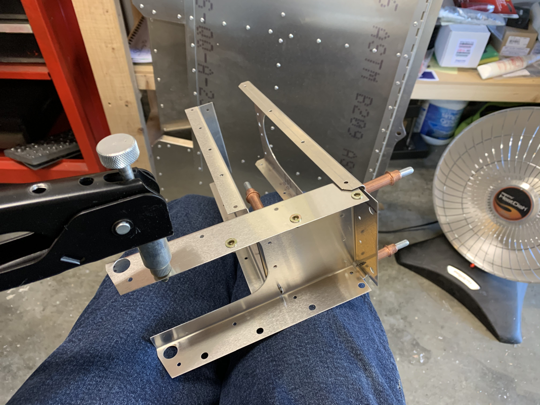
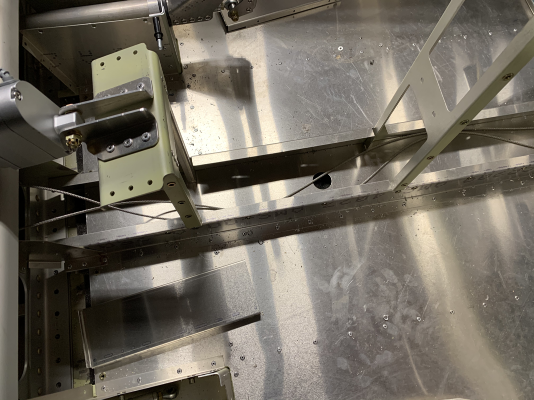
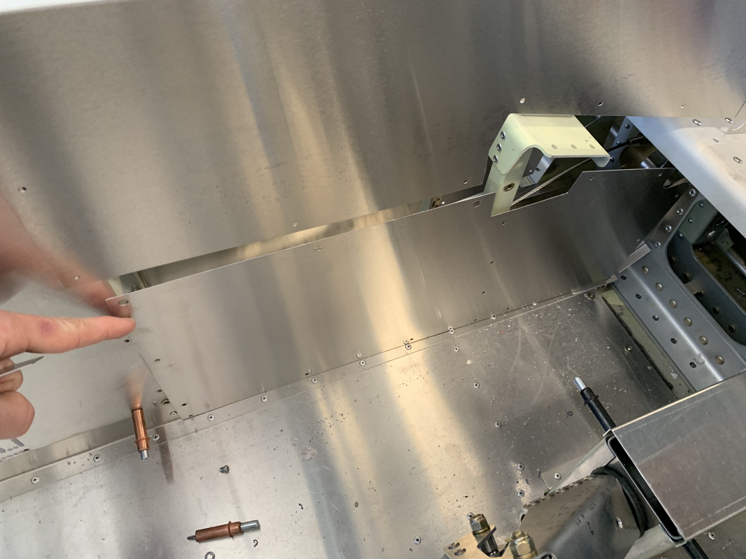
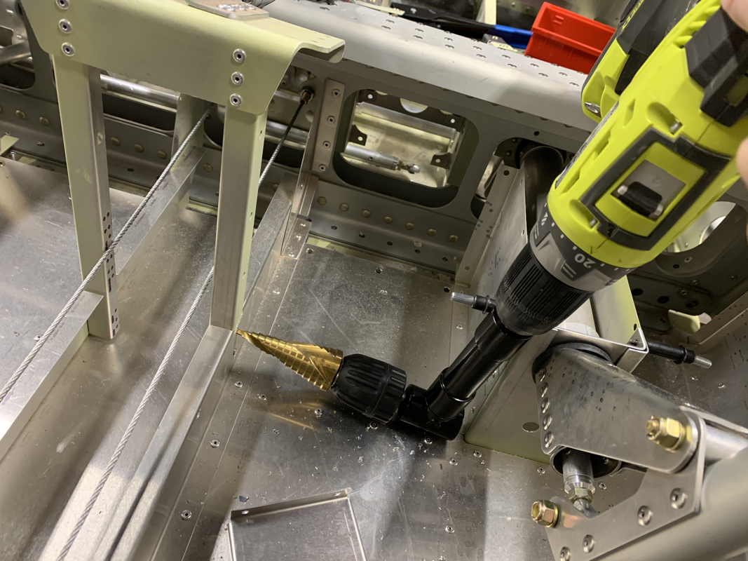
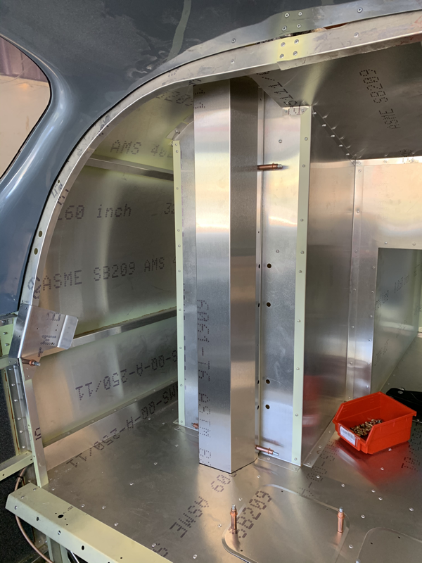
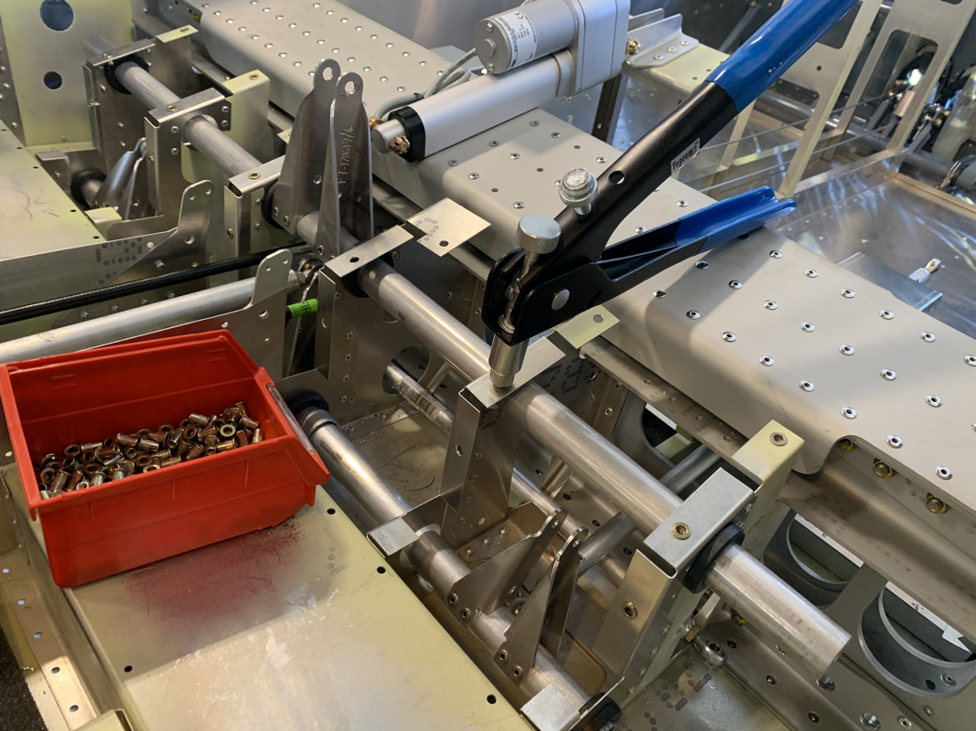
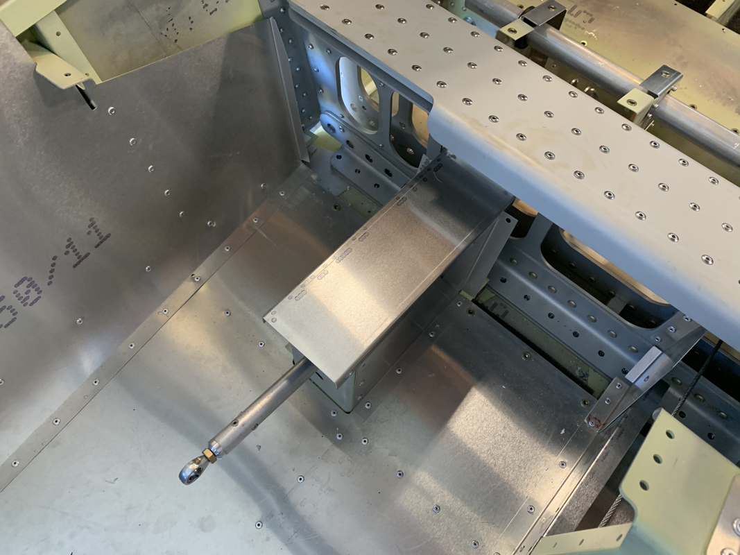
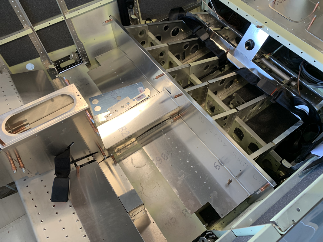
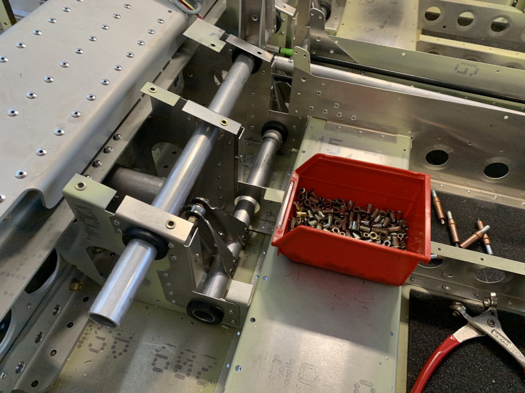
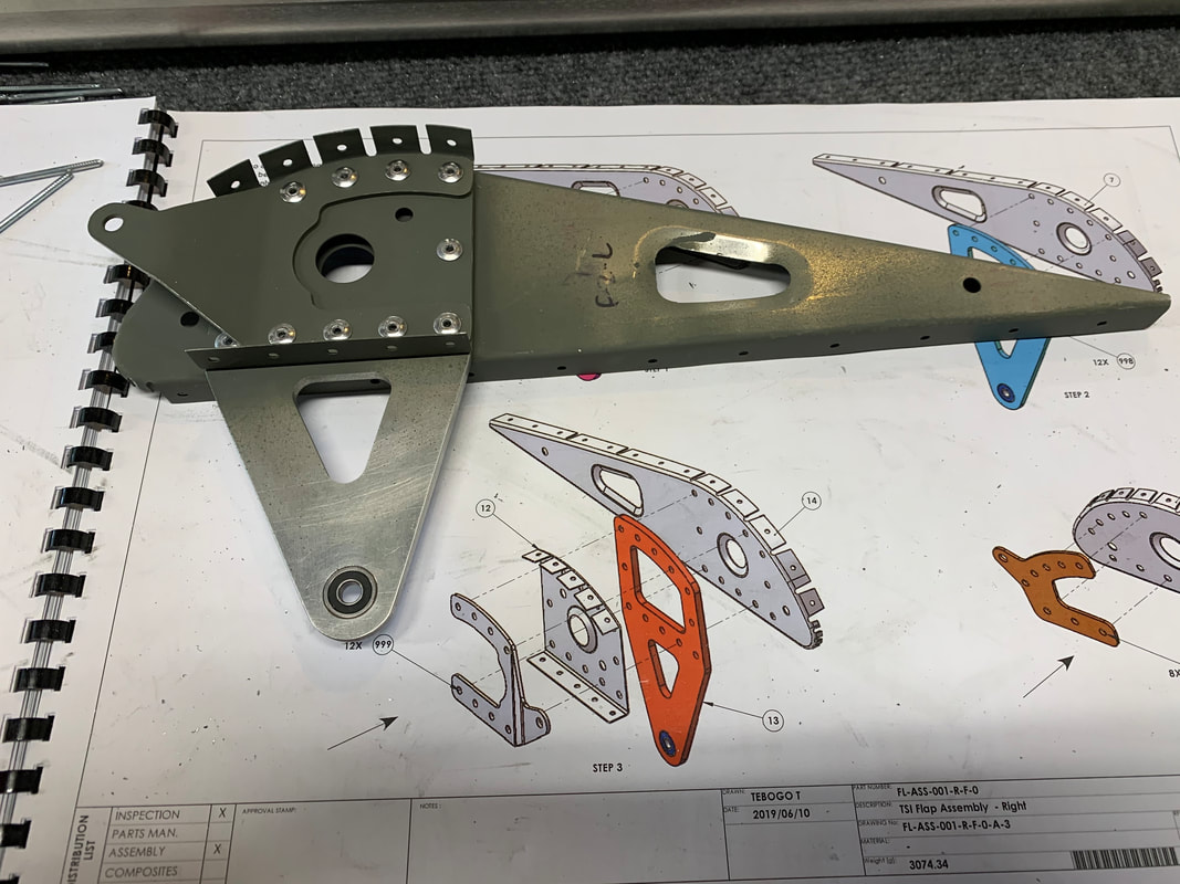
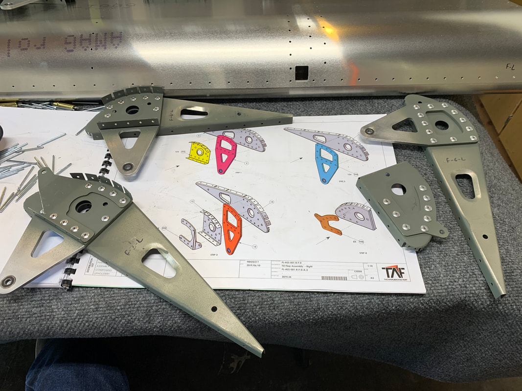
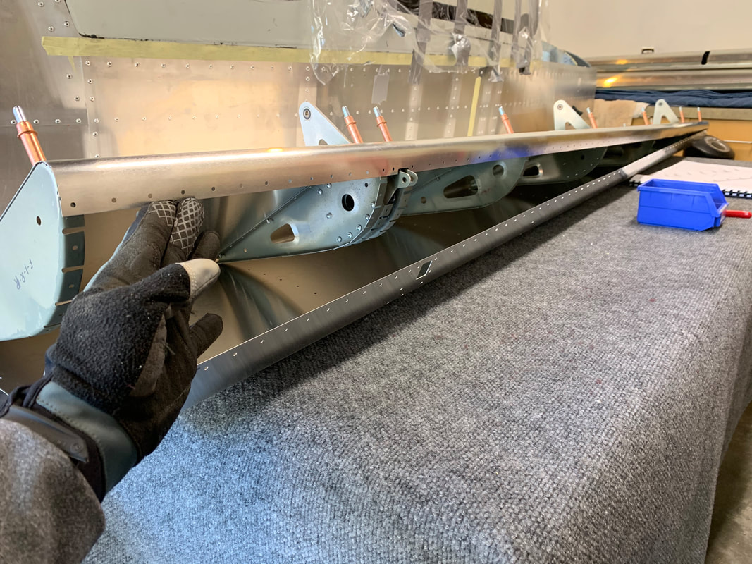
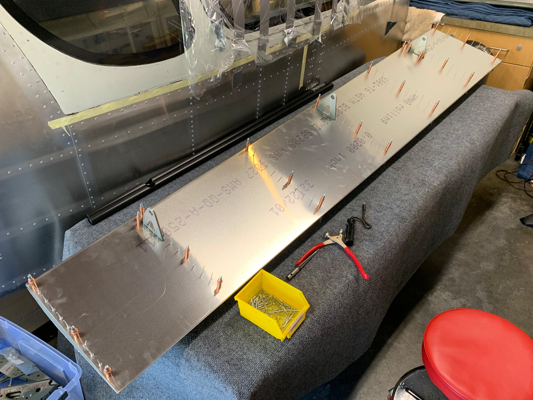
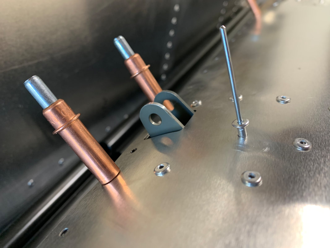
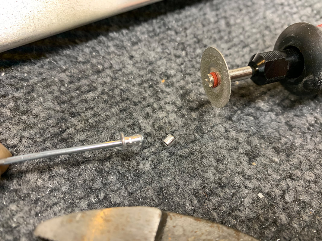
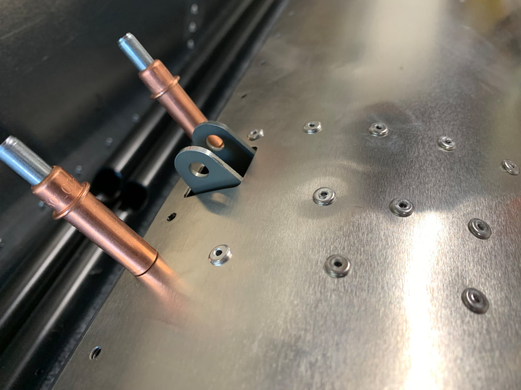
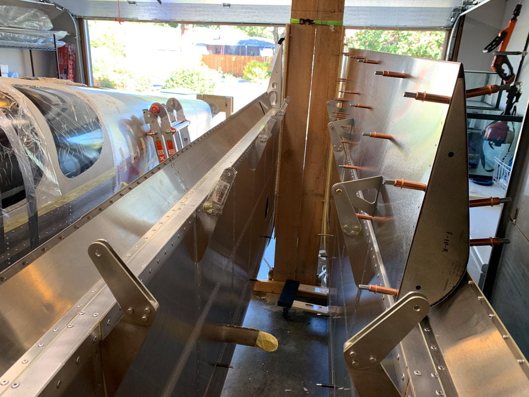
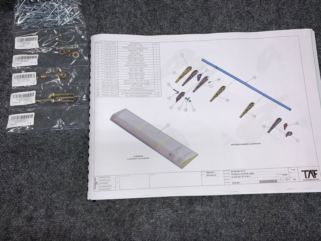
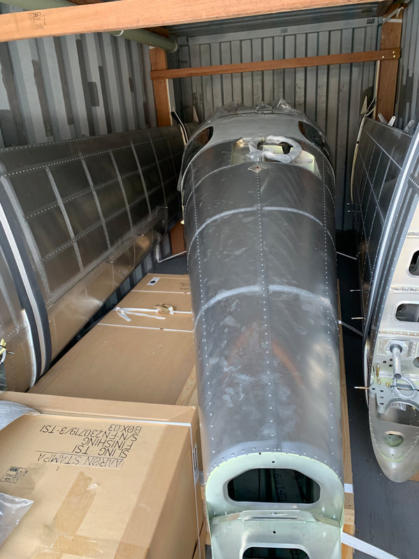
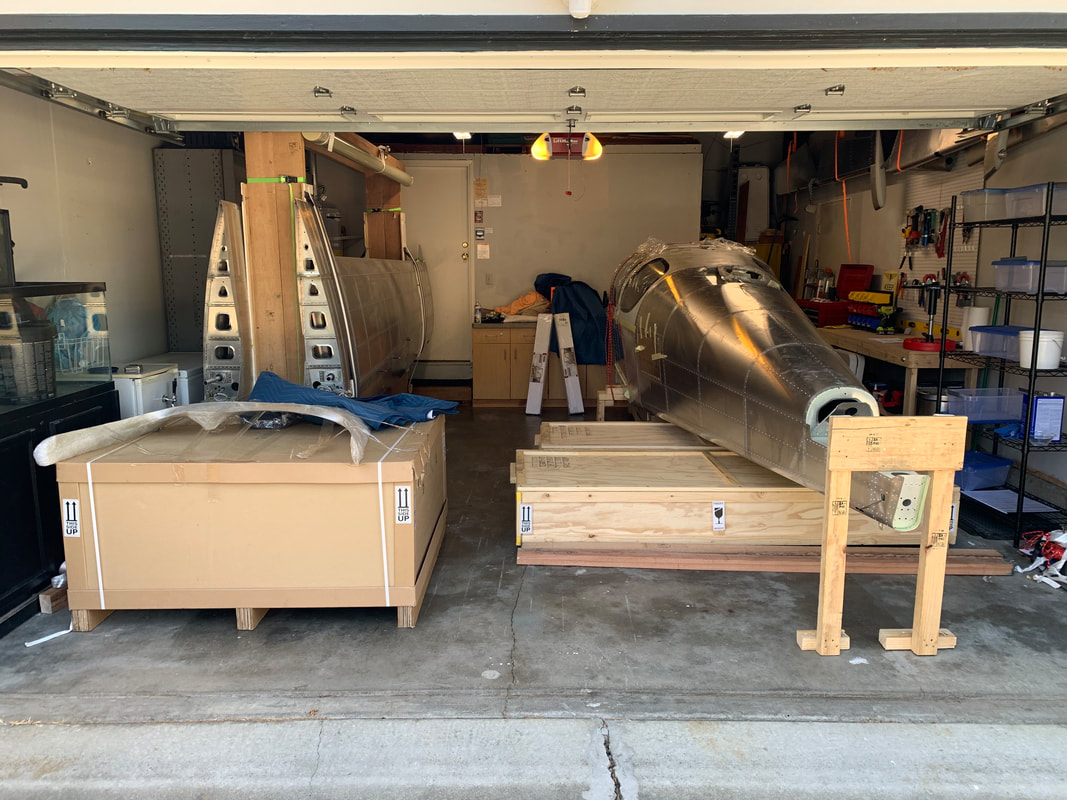
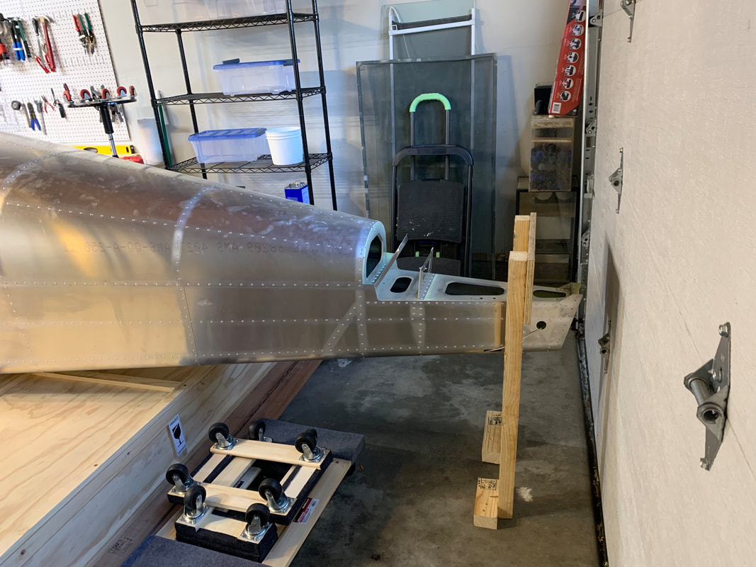
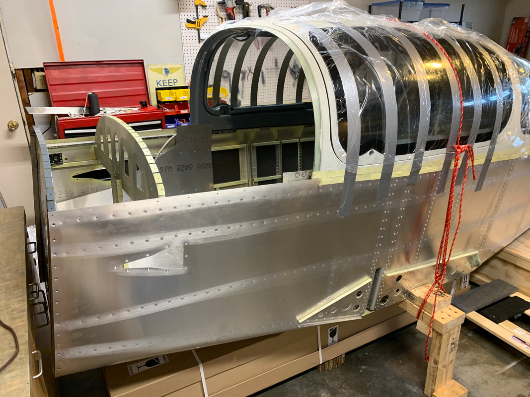
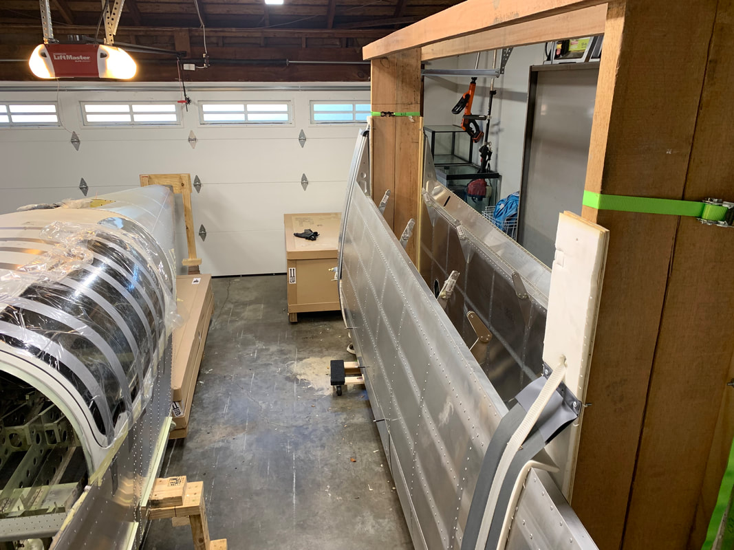
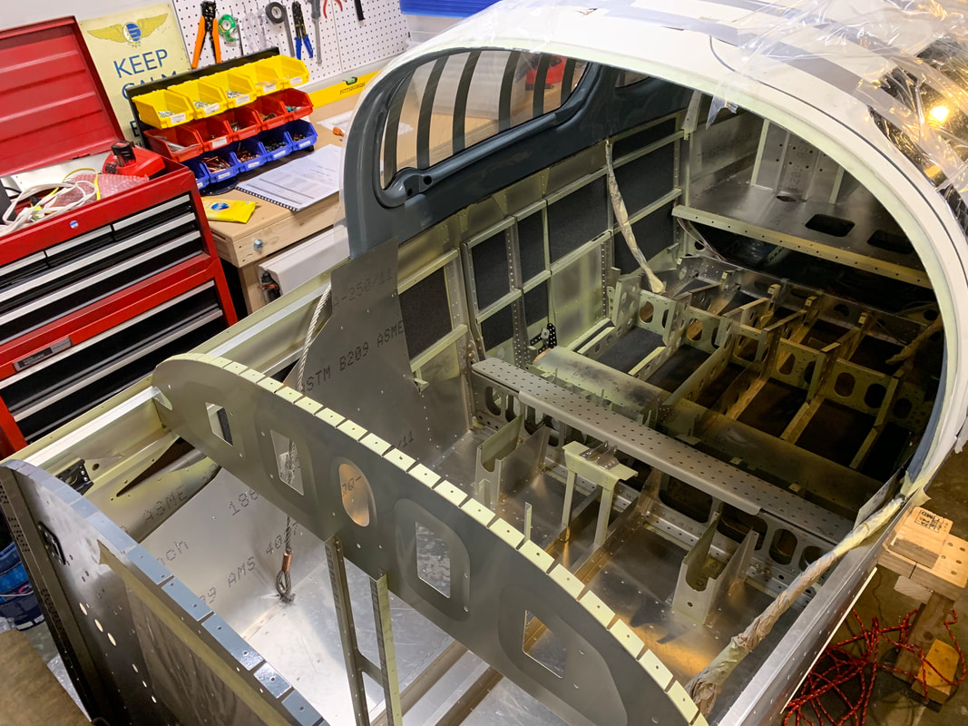
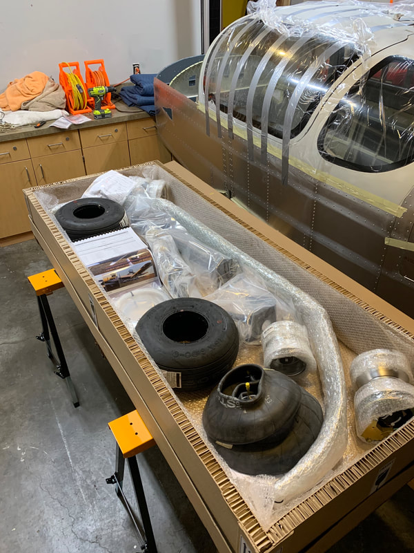
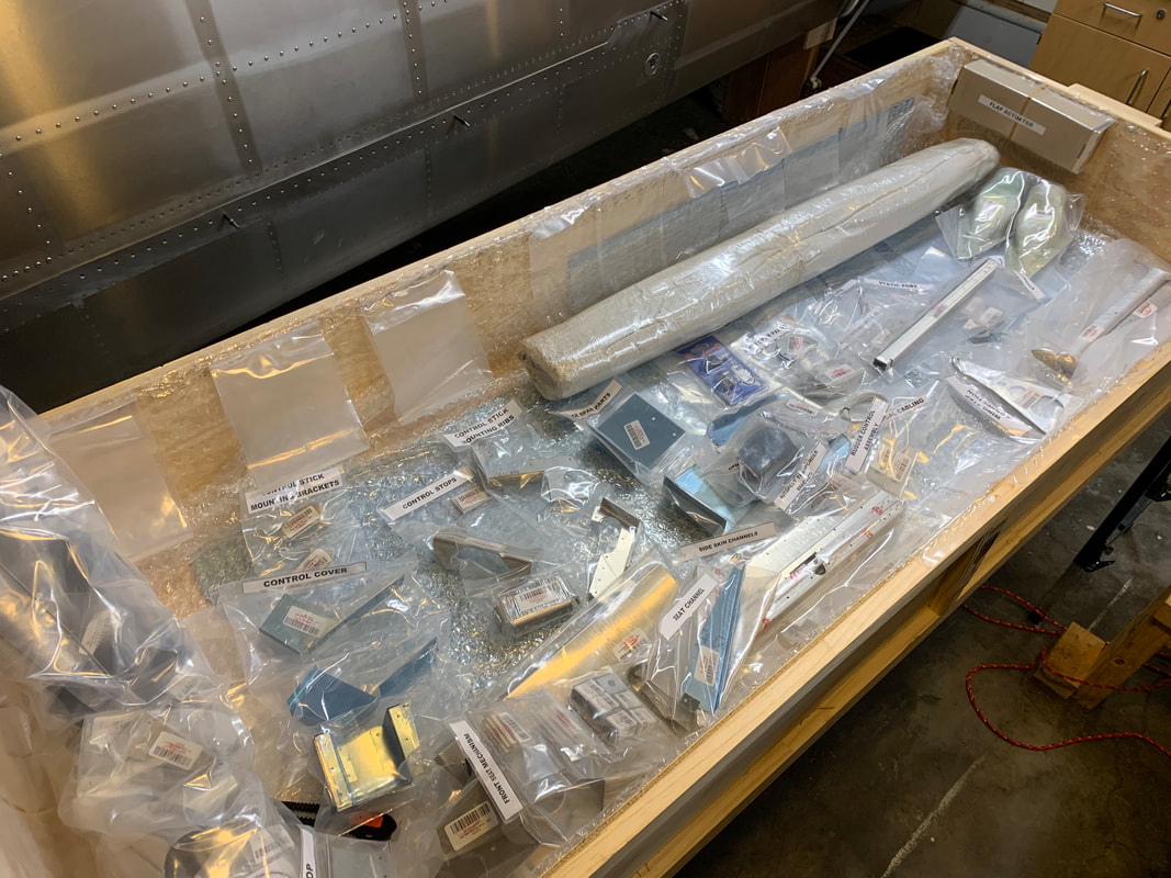
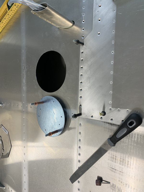
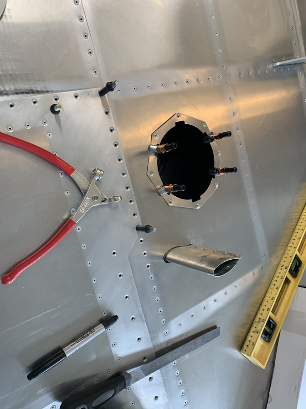
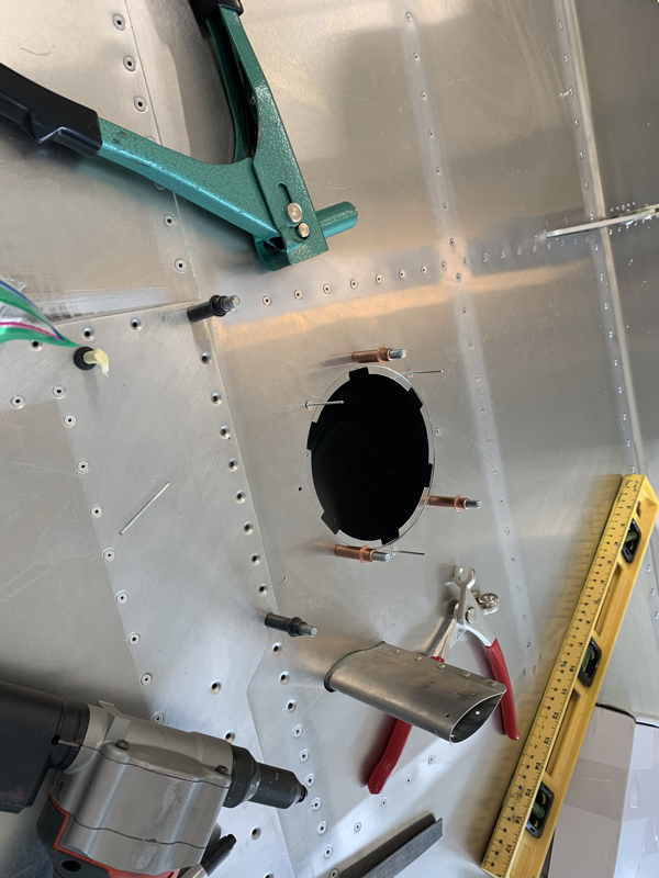
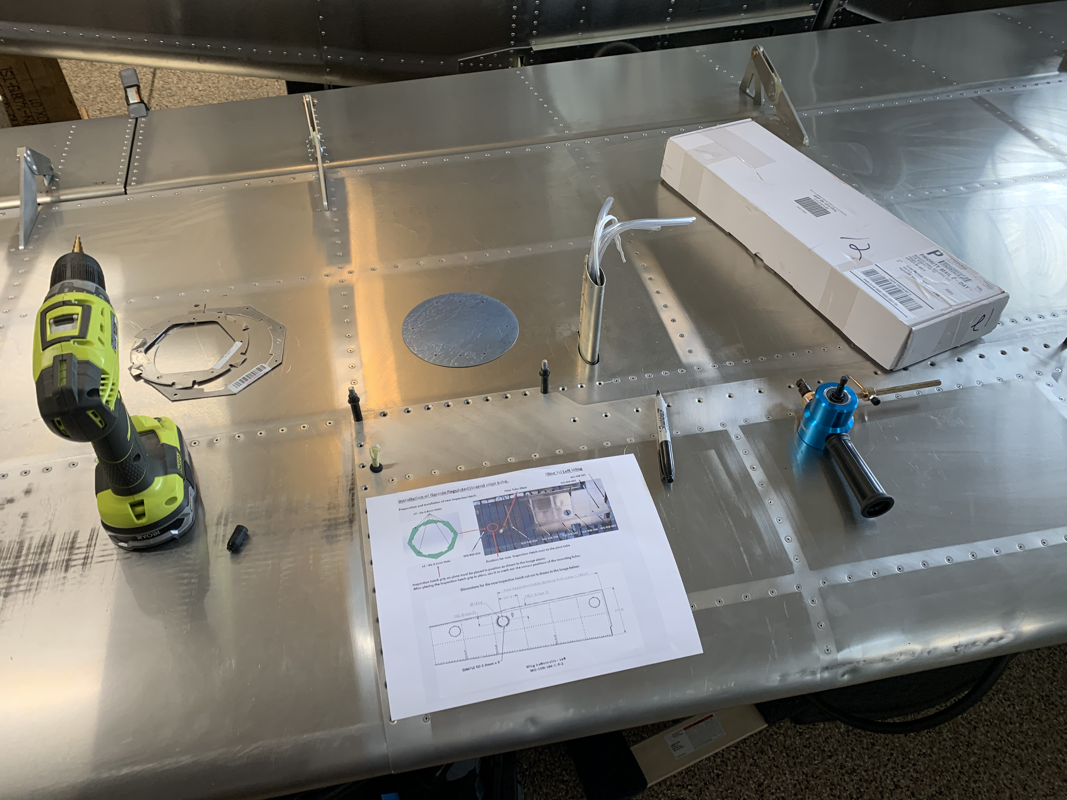
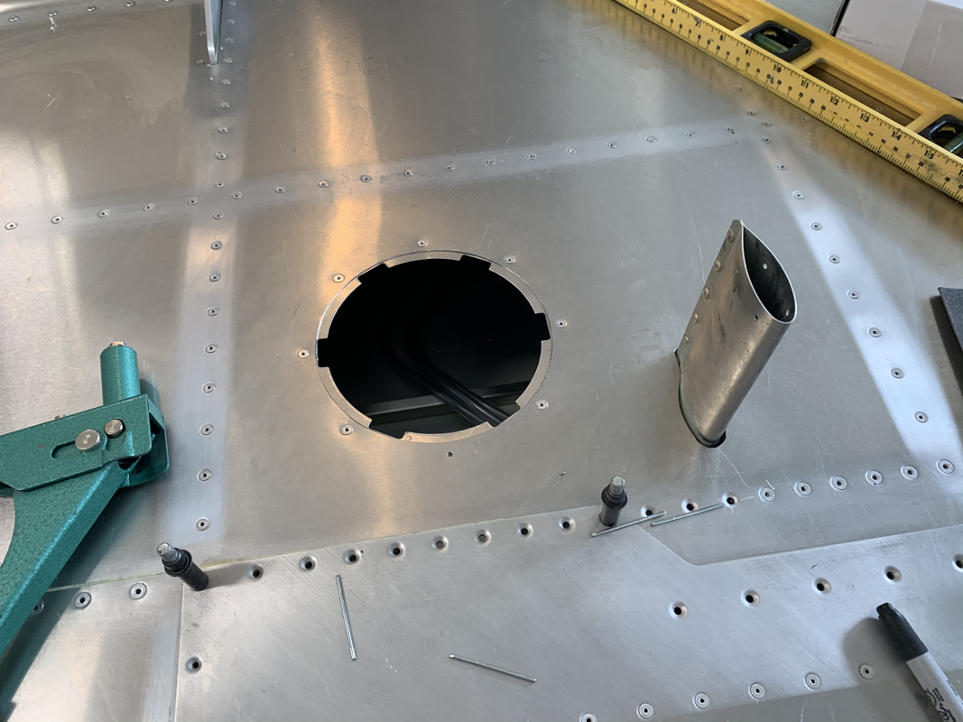
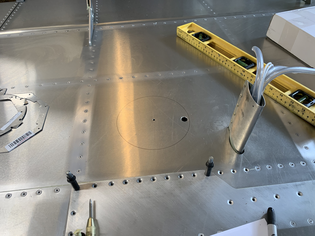
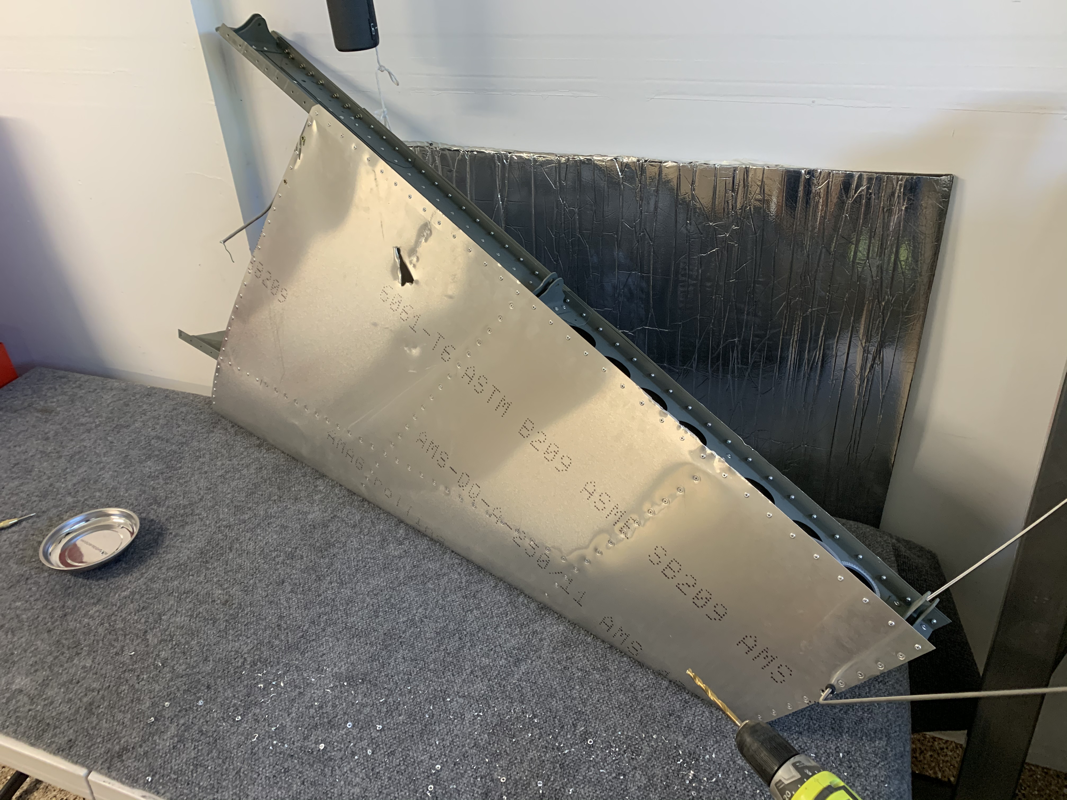
Just a quick update. Installed the rear floor support channels. The skins bend in place if you press on them, so they definitely need them. I also secured the rear parachute cable to the airframe with the AN6 bolt and torqued to spec. I was missing some parts, namely the rear seat strengthening channel and one of the elevator torque tube brackets. I put an order in for those parts, but it was holding up further progress on the fuselage. So I decided I might as well go ‘Old School’ and make the parts to save some time! I had the forward position rear seat channel handy, so I looked at the plans and it seems it’s the same part, just a bit longer in the back. So I trimmed off the end and it fit perfectly. I took a spare piece of aluminum and drew the outline of the elevator torque tube bracket, cut it out, shaved it down and drilled the holes. An hour of effort saved me at least 6 weeks of delivery time from TAF! I was going through the inventory shelves again to take stock of what I have left to do. I came across a bag of parts that didn’t have any reference in the manual, so I sent an email to the TAF technical team. The parts were labeled: CF-CHL-031-X-C-0 Rear Floor Skin Support CF-CHL-042-R-C-1 Side Channel Right and Left I was fortunate enough to get a quick response from the man himself, Mike Bleyth! He sent me a screenshot of the manual and pointing to where these parts go. I figure I might as well post this if anyone else had the same question. Also, in my search I went ahead and downloaded the Sling Aircraft app from the Apple store. I downloaded the manuals to do a search and I actually found a nice treat - Work In Progress Sling TSi Manuals for the Fuselage! They seems to be filling in some nice detail with colored images for construction. These are not available on the Dropbox account yet, so if you want a sneak peak, I suggest downloading the app! Working on some odds and ends this week as I’ve had several items ready to be completed. Ideally I’d like to work on a single item and see it through to completion, but I either have a missing part, tool, problem to figure out, etc so I find something else to work on to move forward. I received a shipment from TAF recently that had the autopilot pushrods, some misc parts and my joystick control assembly. Unfortunately, they only sent one, so I’m still waiting on the other. At least now I can finish up the control pushrods and test it out! I finished up the main landing gear, so it’s all ready to mount. I went with the AN4-26A bolt they provided and just added 2 washers under the head of the bolt to make sure the bolt ends don't hit the wheel spat. I now just have to lift the plane and see how it fits. However, I'm going to have to flip the plane around in the garage with the nose wheel on and angle it for it to fit in the garage. I've also attached the rudder springs. I had to get a flexible drill bit to enlarge the holes for the M5 Rivnut as the luggage floor prevented the drill from fitting. The nose gear took some time to get unbined. The vesconite bushing on the top of the gear was the main culprit, so I took some sandpaper and started sanding by hand and test fitting often. Once I was able to freely twist the bushing, I used a smoother grit to make sure the bushing was contacting the metal with a smooth surface. Next up I'll be finishing up the control torque tubes and connecting the pushrods.. more to come! The factory initially included 2 right flaps in my kit due to some mislabeling. They were able to ship me that along with some other small parts that were missing. Kinda fun to rivet something again, oddly enough. The flap went together within an hour since I already had the ribs prepared and I knew what I was doing. Once that was done I fit it to the wing along with the aileron I had already done, except for the riveting leading edge. I made sure they alignment was good and riveted the leading edge of the flap while on the wing. From there, I checked alignment with the aileron and the wing tip. It required some maneuvering. I put in one rivet in the center of the leading edge of the aileron and checked again. Made another adjustment, added a rivet, made another adjustment.. getting harder now. And placed the third rivet in. Now it was pretty much secure and aligned! Went ahead and did the rest and it turned out great. From there I connected the pushrods to the aileron and flaps, bolted, applied blue loctite and torqued. On to other things! Happy New Year! For the second half of the month I’ve been traveling and spending time with the family, so not much progress on the plane recently. I did find a couple days before the new year to start working on the landing gear. First I started putting together the nose gear, thinking this would be a quick install. It turned into anything but quick. The first issue I ran into was the alignment of the long bolts that hold in the bushings. I had to run a drill through the brackets in place, but without the nose gear in place to be able to align the drill. When I put the nose gear in place it was quite a tight fit. It took some light tapping and fiddling, but eventually got them in place. However, now it is quite hard to turn the nose gear.. I couldn’t imagine a smooth flying experience with it requiring that much pressure to turn. I tried applying some grease to the bushings to help, but that didn’t do much. I have seen other builder’s nose gear and it seems they have sanded off the powder coating to get a better fit. Looks like I’ll have to get the belt sander out with some fine grit to shave off a few micrometers. Update 1/3/20: I spoke with Jean and he recommended to identify which bushing is causing the binding and shaving the vesconite bushing itself instead of the nose gear. The welds that hold the brackets settle and cause a bit of misalignment, so the easiest course of action is to just loosen the bushing a bit to relieve the binding issues. Will provide an update once this is done. The next item was the nose gear tire. It was going along pretty well until I realized I needed to secure a washer and nut on the tire valve stem. I tried this with the tube in the tire first, but couldn’t get enough leverage to push the valve stem far enough into the rim for it to catch. I took the tube out and pressed the valve stem from behind, resting on the rubber mallet. That gave me enough leverage for it to finally catch! From there, securing the bolts and ensuring the tire wasn’t pinched between the rims was a breeze. Now on to the Main Landing Gear! I repeated the same process for the tires and applied the grease to the bearings. I thought securing the axle to the mains would be quick.. it’s only 8 bolts... Well, it seems the predrilled holes from the factory had some alignment issues and I couldn’t get all 4 bolts through. It took me a few hours of light drilling, tapping, removing everything and trying again for it to finally fit. I didn’t want any ‘play’ in the bolts since this is an obvious area of large forces and if there was any movement, it could easily snap a bolt. I finally got one side down and the other side was easier since I knew what I was doing. One thing to note is there is an axle edge spacer that goes between the axle and the main gear to ensure a snug fit. It’s not mentioned in the instructions and I only noticed this after I finally got the bolts to fit, there was a space between the axle and the mains. I put the wedge in and it was a perfect fit! I does look like the supplied bolts (AN4-26a) are a bit too long. I could add 4 washers to the bolt, but that doesn’t seem practical and the bolts will likely hit the wheel spat anyway. The instructions call for AN4-22a, so I’ll have to replace them when I put in my next order with aircraft spruce.. I had my back seats cleco'd and ready to rivet, so I set aside the canopy door puzzle and decided for a quick win. I riveted the back seat base and attached it to the seat back. The fun part was placing it in the fuselage and seeing it all fit! I did have to figure out where to install the back seat stops, as they are not mentioned in the instructions. After a bit of a game of tetris, lining up rivet holes and figuring out the positioning of the stop, I cleco'd it in place. I confirmed on another builder's blog of the positioning. However, the position isn't so easy to get to since I have the QuickBuild and it looks like I'll have to drill some holes in the fuselage ribs. I figure it's about time I climb in the plane and getting to work in there! I was feeling up for a challenge.. and man, did I get it. I started working on the canopy door gas struts and the latches. There aren't any published instructions out there for the TSi, yet, but I was able to get a 'Work in Progress' instruction set from the factory to help move things along. First problem I ran into is that when I drilled holes through the support notches for the gas struts, I didn't drill them at the smallest point. I was thinking I'd want the hole to be a bit closer to the frame for additional support, however the supplied bolts are a bit too small. Not a big deal, but I'll aim the drill a bit differently on the other side. Drilling through the material, it is quite solid. I moved on to try to figure out the latch system. I had to size up the hole for the door handle and drill the two holes on either side to secure it in place. However, it seems the larger hole isn't exactly centered, so the bracket on the back side was catching on the interior frame. I'll just need to shave away a quarter inch to get it to fit snug. I was moving to assemble other parts, but I was missing some important tension pins. I asked the factory and confirmed the size, 3 x 10mm. I was able to source some at Lowes, but will need to shave down to length once inserted. I'm quickly running out of inventory on my shelves! I'm kinda glad I pulled the trigger on the avionics, I just hope it doesn't take the whole 3-4 months of lead time to get everything in. That would mean some down time, unfortunately. I started working on the Throttle and Brake Controls to get them mostly assembled. I am keeping the center console channel undone for a while so I can run wires, but I figure I might as well get parts pre-assembled and out of bags. The brake and throttle went together easily, but it looks like I'm missing some parts. Of course they are small things, like one Castle Nut and one Bolt Bushing used for the throttle cable. Speaking of missing parts, I did get a shipment in from Aircraft Spruce with some bolts I needed to finish up the front seat and the rudder pedals! Nice to finally check those off my list. Started working on the back seat base. The instructions were pretty clear and things were cleco'd together in relative short order. I did run into some alignment issues of the pre-drilled holes. Some I had to drill fresh, others I just had to ream out to get a rivet in. I've been chatting with MidWest Panel Builders about the avionics package and have made my decision. At first, I was going to go with the full Advanced IFR Package, but after a bit of sticker shock and reevaluation of what my needs truly are.. I'll be going with the Basic IFR Package with only one G3X Screen. The GNX375 doesn't have a NAV radio included, like the GTN650, but the cost difference just doesn't seem worth it for something I will probably seldom use. I do have the VOR antenna already mounted in the tail, but I figure I can run the wires and have them handy if there's a future owner that has different needs. I checked all the airports that I plan on flying into and there's more GPS approaches than there are ILS, with the same minimums. If I do have an avionics or GPS failure, I could just use the Sporty's SP-400 handheld radio or similar to get a Localizer / VOR fix. I don't foresee too many other pilots in the right seat needing to fly the plane and I have been wondering where in the world I'd be placing my iPad since I use ForeFlight quite often. With a glovebox option, I can store important items, such as snacks, backup handheld radio, flashlight, etc.. For mounting, I can place a ball joint mount on that side and have the iPad floating in front of the glovebox. It also serves as an in flight entertainment screen for the kid. ;-) Initial deposit is submitted and it's looking like up to a 4 month lead time, which gives me time to finish up the fuselage and run some electrical wires. Now that that's done, the hard part is deciding on an N number! Avionics GARMIN G3X 10" SCREEN GNX 375 NAVIGATOR GAD 29 ARINC 429 INTERFACE GTR 20 COM RADIO GMC 507 AND 2 GSA 28 AUTOPILOT SERVOS GAD 27 FLAP AND TRIM CONTROLLER GEA 24 ENGINE MONITOR GMA 245R BLUETOOTH AUDIO PANEL DESCRIPTION OF WORK G5 BACKUP WITH BATTERY 2 - IBBS BACKUP BATTERIES LRU KIT INSTALL AND CONNECTOR KITS COM/TRANSPONDER/GPS ANTENNAS LASER ETCHED TOSTEN GRIPS GAP 26 HEATED REGULATED PITOT Harness, Rack and Panel CUSTOM MADE PANEL,CUT, COAT, ETCH WITH GLOVEBOX PANEL DESIGN AND BUILD AVIONICS AND ELECTRICAL WIRE HARNESS 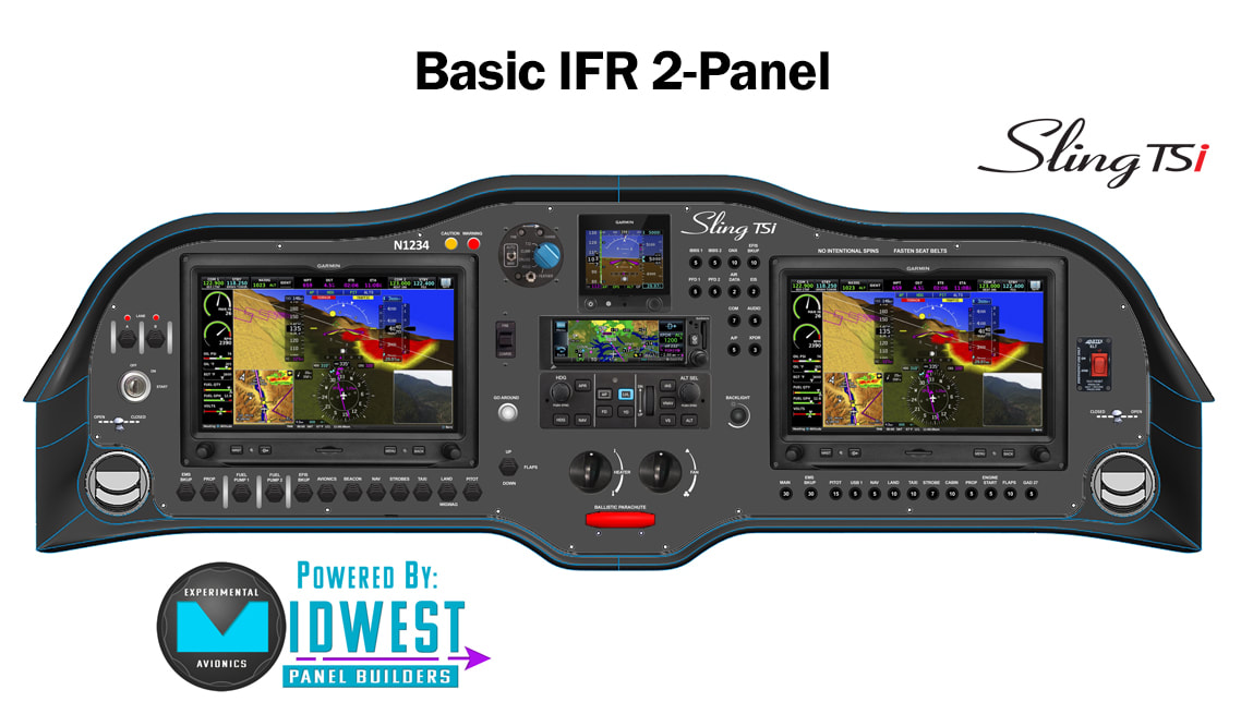 The next pile of metal on the inventory shelves was the back seat. I inventoried everything and laid out the parts I need, from there it was just a matter of clecoing everything together. I started with the seat back rests and will do the bottoms next along with the seat brackets. The only issue I had was the bottom angled channel where some holes didn’t line up. I’ll just drill new ones since the holes are offset about half way. A difficult piece to put on was the last channel that fits between the head rests. Since it has to fit over the skins, it was a tight fit. Had to use a rubber mallet to get the holes cleco’d into place! With the goal of clearing some inventory from the shelves, I picked up some components that were relatively quick to install. The flap actuator is held on by two bolts, so I placed it in there and temporarily secured it. I am having some friction issues on the control tubes while secured in the frame.. will need to trim the brackets that hold the bushings a bit to make them move without much effort. Saving that exercise for another day. For the heater, I measured and drilled the mounting rivnut locations. Since I was drilling through the firewall, I measured and checked at least 5 times! Didn’t want an errant hole to plug up.. Drilling the 32mm hole for the bushings was made easy with a metric step drill bit I found on Amazon. Once done I just pulled the hoses through and secured the hose connector with some hose clamps. From there, I moved on to the front seat rails. Only a few components there, so I secured in place with clecos. I’ll be getting the missing rudder pedal bolts from Aircraft Spruce tomorrow, so I figure I cleco them in place. I’ll connect the pushrods and rudder cables as soon as the bolts arrive. The next stack of parts on the inventory shelf was the heater. This also has the newer style instructions, so it is relatively easy to follow. After inventorying the parts and having enough to proceed, I went ahead and connected the brackets and hose to the heater. You have to cut the hose to fit in the valve, while trying to keep the hose ends parallel and the same length. The instructions call for creating some decent sized holes (32mm diameter for the hoses) in the firewall, have to get a metric step drill bit. Should come in shortly from Amazon. The Rudder pedals came with relatively few parts, so I thought this would be a quick one. Unfortunately, I’m missing some AN4 bolts that hold the stops in place. While I wait for that, I’ll be priming the bottom plate and working on removing any friction from the bushings. There were 2 points where there was still some adhesive left from the tape when these were powder coated. Some acetone made some quick work of getting rid of that and there was much better movement in the pedals. I am working on reducing the inventory of parts on my shelf before I really dive into the fuselage. I decided to start on the seats and it was nice since there are the newer style color instructions available. Putting the parts together for the seat was pretty straightforward, the only issue was that I only had enough parts for one seat. Missing some countersunk metric screws and a particular sized bolt for the seat mechanism. I got as far as I could and will just order the missing parts online. For now, I just put a list of missing items in a bag with other loose items and will be able to quickly finish it up when the parts arrive. I figured I was about to be finished with the right wing and wanted a better wing rack to place it on. I decided to build one off the EAA instructions with some spare wood that I had in the garage. It’s not my best work, but it’s sturdy! Also, I was down in LA for work last week and was able to stop by The Airplane Factory in Torrance. Always good to see the guys and Barry was kind enough to take me out to lunch. While I was there, I met several other folks building or helping build Sling 4’s and TSi’s. Love talking shop! Some great advice and tips for future steps in the build process. One thing I saw there was a parts board, which is perfect for making it easy to find small parts in the inventory! I previously just had all the parts in plastic storage containers, but often had to dig through them to find that ‘one’ missing part. That was much easier to build, just screwed in some small wood planks on the side and stapled the parts to the board. Viola! Next up on the right wing is to place the landing lights. In the QuickBuild, they supplied 3 wires for the landing light. I assumed that this meant there should be an inner and outer landing light positive line and a shared negative line. I first had to determine which lines led to ones on the other end, pretty easy to do with a battery and voltage meter. Once the lines were identified I used my label maker to print out labels for each. I then soldered the negative line to 2 other wires and covered with heat shrink. Placing the lights took some time as the angle isn’t that easy for holding everything in place and fitting the screws. It all eventually fit after some finagling. So I riveted the leading edge while the Aileron was braced and flat on the table. However, when I put it on the wing, I was disappointed to see there was about a 3-4mm deflection. I went ahead and drilled out the rivets and reached out to Jean if he had any tips. Of course he did! He suggested doing one rivet at a time, starting in the center of the Aileron. With 1 rivet done in the center, I was still able to adjust for any twisting, but it was a bit more difficult to move. I then reamed the holes to the left and right of the center rivet and riveted those holes. I checked alignment again and it was still spot on. I continued the process of reaming out and riveting from the center and the Aileron stayed aligned! Once that was done, I fit it to the wing and ran into the issue of the outer rivets rubbing against the wing bracket. Jean said that sometimes the wing brackets are a bit under bent. The real fix is to bend the wing bracket inward. However, after a few hard pushes, there wasn't anyway I was going to be able to budge that thing. So, I settled on adding 2 regular sized washers in between the aileron and wing bracket to allow for adequate spacing. Now it moves quite well! I measured the aileron movement and it looks like I have approximately 26 degrees deflection in either direction. With the help of the wife, I was able to move the wing to the table. The garage is starting to feel like a game of Tetris as the space is a bit limited. Not the biggest deal, but I am sure looking forward to moving to a bigger house next year in Colorado. The flaps and ailerons went on easily. I checked the alignment and had no major issues since I kept the leading edge unriveted. Once I felt the alignment was good, I placed the rivets in and started popping them from the center of the flap/aileron outward to avoid any inadvertent twisting. The Ailerons did have a slight twist toward the tip of the wing, so I had to de-rivet the leading edge. Jean suggested to line up the Aileron on the wing, then rivet each hole one by one and check alignment on the way. I also placed the pushrods in the wing and secured them with the bolts. I then tested the maneuverability of the components and the flaps had no issue. The Aileron, however, seemed to catch at the end of the wingtip where the brackets rub against the rivets. Looking at either bending the brackets or adding spacers. I then test fit the wing tip and discovered the form factor was narrower than the wing’s thickness. Not knowing any good tricks for expanding the fiberglass tip to the form and allow for match drilling/riveting, I reached out to Jean and he recommended a great idea. Grab a styrofoam block and press it against the end of the wing to get the outline. Then, cut out the foam and glue it in place in the fiberglass wing tip to get the right form. Ill be able to drill and rivet once the fiberglass tip is lined up with the metal. With the great advice from Phillip on locating the AN4-16A bolts provided in the finishing kit, I was able to finish up the Ailerons. I am quite surprised how much hardware there is in the finishing kit, really. When in doubt, look in there! That’s where a whole host of nuts and bolts live.. My father-in-law was visiting this weekend and he was interested in the process. We split up the tasks of clecoing, reaming, putting in the rivets and popping the rivets. It was quite nice to have an extra set of hands and made quick work of the Ailerons! A couple things to note, the bar that goes inside the leading edge of the Aileron was straight, however the rivet holes that hold it in place to the skin were not. I tried clecoing those holes and the whole skin had a pretty bad bend. Instead of using those holes, I'll just drill out new ones to make sure it is held in place with the Aileron perfectly aligned. Also, the brackets at the edge of the Aileron are only depicted on the first page, but not in the step by step page. Other than that, it went pretty smoothly! Since I was blocked on the Ailerons from the missing bolt, I decided to turn the page to the next item - the flaps. As I laid everything out, I finally had all the parts for the ribs, bolts, etc. However, it looks like I received two of the right side flap skins. Doh! I put in an order for the left side flap skin with the factory. They are estimating a shipment to come in at the end of the month. At least I can press forward with the left side and get the ribs all done for both. I cleaned, scuffed and primed the ribs and skin and started assembling the parts. Most of the flap ribs were pretty straight forward. However, there was one rib that had a 2 step process - there is an overlapping design that would make the rivet holes inaccessible if done all in one step. Once I figured that out, things were quite smooth. I fitted the ribs in the skins, cleco'd, temporarily fitted to the wing and checked alignment. Everything seemed to be in order, so I started riveting the skins to the ribs, leaving the leading edge unriveted per instructions for the final alignment check. There was an issue with riveting the flap skin, it seems one of the brackets was blocking the rivet. I had to shorten the rivet to get it in. As soon as I get the other flap skin and the missing bolts for the Ailerons, I'll fit everything on the wing and do the final alignment check with all the parts. Back to work! Feels good to get my hands dirty again. After working through the overwhelming feeling of having suddenly so much to do, I started to focus in on the wing components first, as that is the recommended order. I unpacked and inventoried the wing components crate and checked off everything on the packing inventory list as I found them. I decided I will be following the same method I used for the Empennage kit for cleaning, scuffing and priming. I know this does take some additional time but since these are exterior, and pretty critical parts, I figure it's worth an extra hour or so of my time. I finally got to the point where I was assembling the Aileron ribs and tried to find the AN4-16A bolt that connects the Aileron to the push rod in the wing. Unfortunately, it was not included in the inventory packing list, so it wasn't sent - even though it is referenced in the instructions. I tried to use the AN4-11A bolt provided in the inventory, but as you can see in the last photo, it isn't long enough to get the threads past the spacers and into the lock nut. I put an order into the TAF ordering system and Perry said they'll send the bolts with the Service Bulletin 14 Rivet replacements next week. Until then, I'll start on the flaps. UPDATE 11/2/2019 - Since I posted this in the Sling Builders group on Facebook, Phillip was kind enough to give me a pro tip on where to find the AN4-16A bolts - in the finishing kit! The one box I haven't inventoried yet. Thanks Phillip! You can find his blog here. Love having the active builder's community out there! Woo Hoo! It's finally here! It was feeling like Christmas morning for me when I received the call to schedule delivery of the shipping container. After waiting a whole 7 months since I put down my deposit, there was quite a bit of anticipation built up! My neighbors were kind enough to help me unload the plane into the garage and help me fit things in there. Once I saw the size of the plane, I was quite nervous how it would all fit. Luckily, I had about 2 inches of clearance from the garage door. ;-D I spent the remainder of the day trying to organize things and set up a small workspace for me to start assembling items. I also had to get another storage rack to fit all of these additional parts once I get them out of the boxes! Looking forward to getting started up again! So I had to figure out how to best fit the VOR Antenna and run the wire through the ribs since the instructions only account for a Tail Position Light OR a VOR Antenna. This is to ensure there is no electromagnetic interference of the VOR Antenna. However, with the low power requirements of modern LED lights make this a bit less concerning, so I opted to do both. In order to accommodate the second wire running through, I drilled a hole on the top rib and put a rubber grommet through. From there, I could keep the wires separated on the front and back of the VS. From there, I was able to prime and apply the skin to the ribs, cleco in place and check the alignment. Straight as an arrow, so I began riveting one side. I checked alignment again and was still good, so proceeded to finish up. It was a bit tricky fitting the VOR Antenna. The antenna base is a bit tight against the rib, and it did cause a bit of a bump around the antenna on the skin. I don’t see that being a huge issue really. I did have to shorten 2 rivets to fit near the antenna. Glad to be done with the Empennage Kit! Now, I await the arrival of the QuickBuild Kit expected in mid to late October. Until then, my wife gets custody of the garage. ;-) |
Archives
September 2021
Categories
All
|


 RSS Feed
